Spirax Sarco Spirax Sarco M10Si/M10Si2RB/M10Si4RB ISO Ball Valves
¥1,147.00 – ¥6,000.00
Brand authorization
- Rapid response service
- Professional team support
- Flexible return and exchange policy
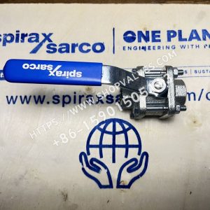
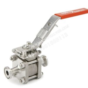
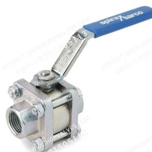
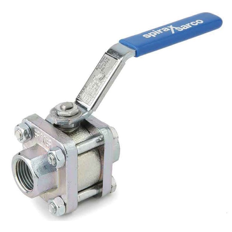
Spirax Sarco Spirax Sarco M10Si ISO ball valves (DN¼" to DN2½") are three-section ball valves, which as isolation valves cannot be used as regulating valves. Suitable for steam and other industrial fluids, they can be used in environments ranging from vacuum to higher temperatures and pressures, and are equipped with a lockable full handle that supports direct access (threaded and welded types only) without removal from the pipeline. Manual/remote control can be safely and easily accomplished with this ball valve, as the body does not need to be disassembled, and integral ISO body mounting automates the valve without compromising seal integrity.
Available Models
| Available types | Specification |
|---|---|
| M10Si2__ISO | Zinc-plated carbon steel body, PDR 0.8 seat |
| M10Si3__ISO | Stainless steel body, PDR 0.8 seat |
| M10Si4__ISO | All stainless steel, PDR 0.8 seat |
Note: In the naming convention, FB stands for full bore and RB stands for reduced bore.
Standards and Certificates
- (an official) standard: Fully compliant with the European Pressure Equipment Directive 97/23/EC, with marking available on request.
- Certification: Certificate EN 10204 3.1 available.
Note: If test certificate is required, please specify when ordering; Maximum working pressure may be limited by flange standard, please consult Spirax Sarco for details.
Sizes and pipe connections
full bore
| caliber | Pipe connection method | Criteria for correspondence |
|---|---|---|
| 1/4", 3/8", 1/2", 3/4", 1", 1-1/4", 1-1/2", 2" | flangeless | DN15 to DN50, ASME (ANSI) Class 150 |
| 1/4", 3/8", 1/2", 3/4", 1", 1-1/4", 1-1/2", 2" | Threaded, welded (BSP, BSPT, API/NPT, BW, SW) | ASME (ANSI) Class 300, EN 1092 PN40 |
Reduced diameter
| caliber | Pipe connection method | Criteria for correspondence |
|---|---|---|
| 1/4", 3/8", 1/2", 3/4", 1", 1-1/4", 1-1/2", 2", 2-1/2" | flangeless | DN15 to DN65, ASME (ANSI) Class 150 |
| 1/4", 3/8", 1/2", 3/4", 1", 1-1/4", 1-1/2", 2", 2-1/2" | Threaded, welded (BSP, BSPT, API/NPT, BW, SW) | ASME (ANSI) Class 300, EN 1092 PN40 |
Pressure and temperature limits
| parameters | instructions | numerical value |
|---|---|---|
| PMA | - | 100 bar g@60°C |
| TMA | Maximum permissible temperature | 260 °C @0 bar g |
| TMA | Minimum permissible temperature | -29 °C |
| PMO | Maximum working pressure under saturated steam | 17.5 bar g |
| TMO | Maximum working temperature | 260 °C @0 bar g |
| TMO | Minimum working temperature | -29 °C |
| - | Design maximum cold hydraulic test pressure | 150 bar g |
NOTE: Consult Spirax Sarco below -29°C; ΔPMX maximum differential pressure is limited by PMO; this product cannot be used in the prohibited areas specified in the pressure/temperature limitation charts (A - B corresponds to 2" FB and 2½" RB, A - C corresponds to ¼" -1½" FB, RB, and 2" RB).
Technical data
| Technical Parameters | instructions |
|---|---|
| Flow characteristics | Corrected linear |
| a thoroughfare | Full bore and reduced bore |
| leak rate | Test standard ISO 5208 (Class A)/EN12266-1 (Class A) |
| antistatic | Conforms to ISO 7121 and BS 5351 standards |
material (that sth is made of)
| Item | Part | Available types | material (that sth is made of) | Corresponding standards/specifications |
|---|---|---|---|---|
| 1 | valve body | M10Si2 ISO | Galvanized carbon steel | ASTM A105 |
| 1 | valve body | M10Si3 ISO | stainless steels | ASTM A182 F 316L |
| 1 | valve body | M10Si4 ISO | stainless steels | - |
| 2 | bonnet | M10Si2 ISO | Galvanized carbon steel | ASTM A105 |
| 2 | bonnet | M10Si3 ISO | stainless steels | ASTMA 182 F 316L |
| 2 | bonnet | M10Si4 ISO | stainless steels | - |
| 3 | steel ball | - | stainless steels | AISI 316 |
| 4 | tappet | - | stainless steels | AISI 316 |
| 5 | Seat | - | Carbon/graphite reinforced PTFE | PDR 0.8 |
| 6 | Stem seals | - | Antistatic reinforced PTFE | - |
| 7 | splitter | M10Si2 ISO | Galvanized carbon steel | SAE 1010 |
| 7 | splitter | M10Si3 ISO | stainless steels | AISI 316 |
| 7 | splitter | M10Si4 ISO | stainless steels | - |
| 8 | Beethoven's Washers | - | stainless steels | AISI 301 |
| 9 | nut (female component of nut and bolt) | M10Si2 ISO | Galvanized carbon steel | SAE 1010 |
| 9 | nut (female component of nut and bolt) | M10Si3 ISO | stainless steels | AISI 304 |
| 9 | nut (female component of nut and bolt) | M10Si4 ISO | stainless steels | - |
| 10 | Nameplates (unlabeled) | - | stainless steels | AISI 430 |
| 11 | Valve stem nut | M10Si2 ISO | Galvanized carbon steel | - |
| 11 | Valve stem nut | M10Si3 ISO | stainless steels | SAE 1010 |
| 11 | Valve stem nut | M10Si4 ISO | stainless steels | AISI 304 |
| 12 | connecting rod | M10Si2 ISO | Galvanized carbon steel | SAE 1010 |
| 12 | connecting rod | M10Si3 ISO | stainless steels | - |
| 12 | connecting rod | M10Si4 ISO | stainless steels | AISI 316 |
| 14 | video game controller | - | vinyl resin | - |
| 15 | bolt (male component of nut and bolt) | M10Si2 ISO | Galvanized carbon steel | Level 5 |
| 15 | bolt (male component of nut and bolt) | M10Si3 ISO | stainless steels | - |
| 15 | bolt (male component of nut and bolt) | M10Si4 ISO | stainless steels | AISI 304 |
| 16 | nut (female component of nut and bolt) | M10Si2 ISO | Galvanized carbon steel | - |
| 16 | nut (female component of nut and bolt) | M10Si3 ISO | stainless steels | SAE 1010 |
| 16 | nut (female component of nut and bolt) | M10Si4 ISO | stainless steels | AISI 304 |
| 17 | stud bolt | M10Si4 ISO | stainless steels | AISI 316 |
| 18 | stop pin | M10Si2 ISO | Galvanized carbon steel | SAE 12L 14 |
| 18 | stop pin | M10Si3 ISO | stainless steels | - |
| 18 | stop pin | M10Si4 ISO | stainless steels | AISI 304 |
| 19 | Body/Bonnet Gasket | - | O-Ring (EPDM) | - |
| 20 | locknut | - | stainless steels | AISI 316 |
| 21 | Lockable handle | M10Si2 ISO | Galvanized carbon steel | SAE 1010 |
| 21 | Lockable handle | M10Si3 ISO | stainless steels | - |
| 21 | Lockable handle | M10Si4 ISO | stainless steels | AISI 316 |
| 22 | Stem seals | - | PEEK | - |
| 23 | locking plate | - | stainless steels | AISI 304L |
Weight (approximate) kg
| caliber | Reduced diameter | Reduced diameter | Reduced diameter | Reduced diameter | full bore | full bore | full bore | full bore |
|---|---|---|---|---|---|---|---|---|
| - | Threaded/Butt Weld/Socket Weld | PN40 | ASME 150 | ASME 300 | Threaded/Butt Weld/Socket Weld | PN40 | ASME 150 | ASME 300 |
| ¼" | 0.65 | - | - | - | 0.65 | - | - | - |
| 3/8" | 0.65 | - | - | - | 0.72 | - | - | - |
| ½" | 0.72 | 2.30 | 1.77 | 1.70 | 0.95 | 2.60 | 1.87 | 2.40 |
| ¾" | 0.95 | 3.20 | 2.35 | 2.28 | 1.60 | 3.80 | 2.73 | 3.79 |
| 1" | 1.60 | 4.20 | 3.47 | 2.91 | 2.05 | 4.70 | 3.55 | 5.01 |
| 1¼" | 2.05 | 5.70 | 4.47 | 4.15 | 2.75 | 6.40 | 4.76 | 6.50 |
| 1½" | 2.75 | 6.80 | 5.96 | 5.88 | 4.25 | 8.30 | 5.82 | 9.22 |
| 2" | 4.25 | 9.50 | 9.16 | 8.12 | 7.50 | 12.80 | 11.91 | 13.99 |
| 2½" | 7.50 | - | - | 15.85 | - | - | - | - |
KV value
| caliber | Reduced through diameter KV value | Full bore KV value |
|---|---|---|
| ¼" | 2.5 | 2.5 |
| 3/8" | 6.8 | 6.8 |
| ½" | 6 | 17 |
| ¾" | 10 | 36 |
| 1" | 27 | 58 |
| 1¼" | 49 | 89 |
| 1½" | 70 | 153 |
| 2" | 103 | 205 |
| 2½" | 168 | - |
Conversion formula: (C_{v}(UK) = K_{v} × 0.963); (C_{V}(US) = K_{V} × 1.156)
Working torque(Nm)
| caliber | Reduction torque | Full bore torque |
|---|---|---|
| ¼" | 3.25 | 3.25 |
| 3/8" | 3.25 | 3.25 |
| ½" | 3.25 | 5.50 |
| ¾" | 5.50 | 13.25 |
| 1" | 13.25 | 20 |
| 1¼" | 20 | 50 |
| 1½" | 50 | 60 |
| 2" | 60 | 75 |
| 2½" | 75 | - |
The above torques apply to valves for frequent use up to a maximum differential pressure of 40 bar; for valves in a fixed position for a long period of time, the torque may be increased further.
protect and maintain
For detailed information, refer to the Installation and Maintenance Guide supplied with the product.
place an order
- Ordering Example: Spirax Sarco ½" threaded M10Si2FB ISO ball valve.
- Ordering InformationIf the model is not selected before ordering, please provide the use parameters (nominal diameter, fluid properties including nominal pressure/temperature/viscosity or acidity/alkalinity, valve body and spool material); if the model has been selected, it can be ordered directly according to the model; when the use of important occasions or pipeline complexity, it is recommended to provide the design drawings and detailed parameters, and be examined and approved by professional staff.
options (as in computer software settings)
- Self-venting steel ball
- Extended stem (50mm/2" and 100mm/4") for complete thermal insulation
- Oval shaped handle to fit in tight spaces (especially hydrophobic stations)
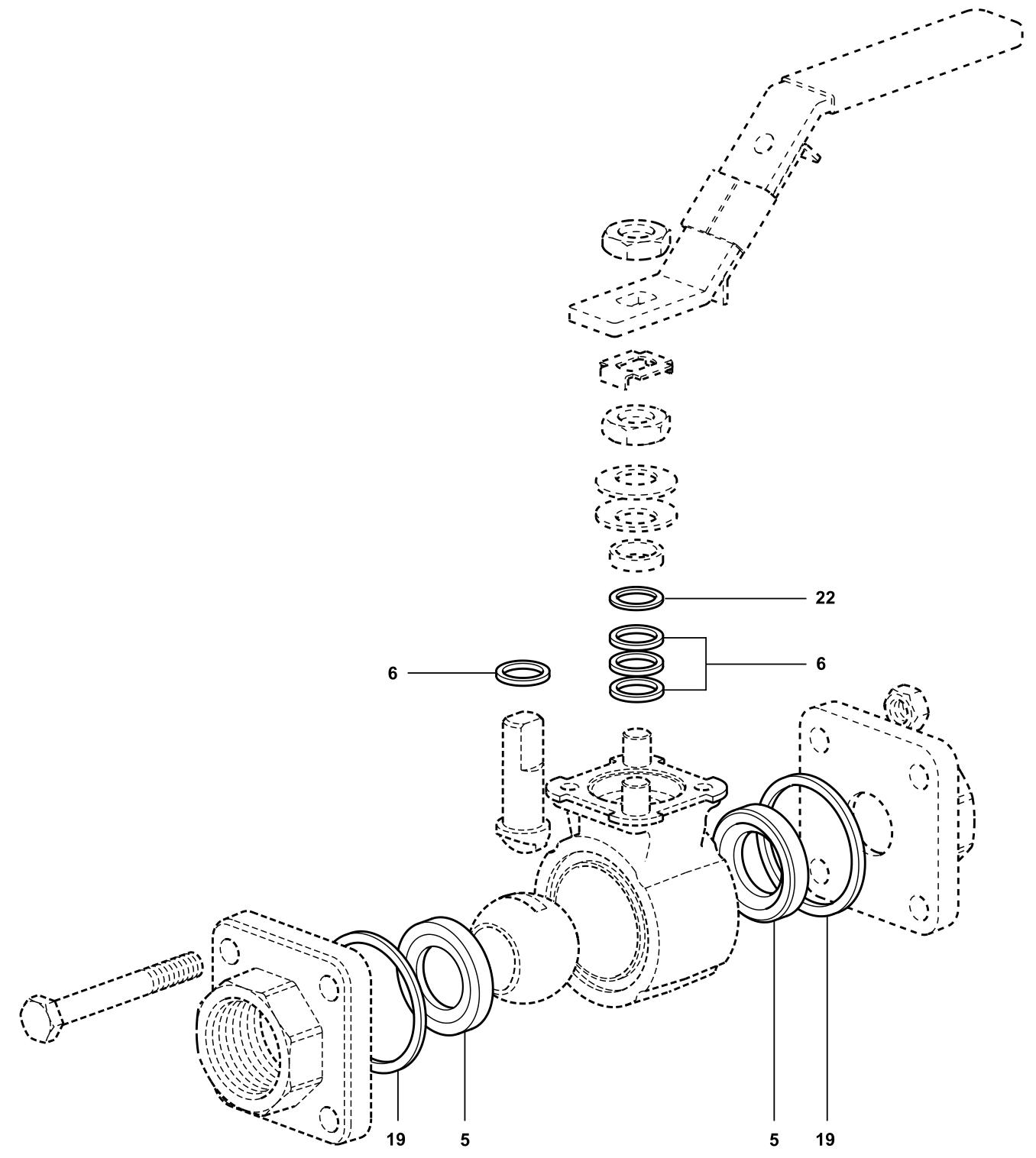
Spare Parts
- Spare parts available: Seat, stem and body seal sets (corresponding to part numbers 5, 6, 19, 22)
- Description of spare parts: Spare parts are shown in solid lines, those shown in dotted lines are not available as spare parts.
- Order spare parts: Order as described above for the type of spare part available, specifying the valve caliber and model number.
- Spare parts ordering example: ½" M10Si2FB ISO ball valve seat and stem seal set.
Installation Precautions
- Inspection before installation: carefully check whether the valve body, ball, stem and other parts are complete to ensure that there are no defects; check whether the seals are loose or damaged to prevent air or liquid leakage.
- Installation location selection: choose an easy-to-operate location for convenient switching and maintenance; also consider the flow path when the valve is opened to avoid unnecessary pressure loss.
- Piping requirements: before and after the pipeline should be coaxial, the two flange sealing surface should be parallel; pipeline should be able to withstand the weight of the ball valve, otherwise need to be equipped with appropriate support; the valve before and after the pipeline blowing clean, remove oil, welding slag and other impurities.
- Valve inspection: check the ball valve sign, identify intact; the valve will be fully open and closed several times to confirm that the work is normal; remove the two ends of the connection flange on the protective parts, check and clean the valve holes (between the valve seat and the ball of even small particles of foreign matter may damage the sealing surface of the valve seat).
- Installation details: either end of the ball valve can be installed at the upstream end; handle-driven ball valves can be installed at any position in the pipeline, with a gear box or pneumatic ball valves should be installed in an upright position (on the horizontal pipeline, the driver is above the pipeline); the valve flange and pipeline flange according to the pipeline design requirements for the installation of sealing gasket; flange bolts need to be symmetrical, one by one, evenly tightened; the use of pneumatic drive, connecting the pneumatic pipeline.
- Special welding requirements: socket welding and flat welding type valves before welding, need to remove the end cap from the valve body, remove the R-PTFE valve seat, the end cap welded to the pipeline, and then install the R-PTFE valve seat and reassembly; disassembly and commissioning before, make sure that there is no medium flow in the pipeline.
- Requirements specific to steam systems: When used for steam systems, a trap needs to be installed upstream of the valve; open the valve slowly to avoid water hammer.
Seal check
After the ball valve is closed, judge the sealing situation by observing the position of the valve stem: if the position of the valve stem is completely contracted, it means that the sealing is good; if the position of the valve stem is protruding, there may be a leakage problem, which needs to be dealt with in time.
Precautions for use
- Use of pressure: need to comply with product specifications, too high or too low pressure may affect normal operation.
- Temperature range: Material and sealing performance should match the fluid temperature range to avoid damage or failure to work due to too high or too low temperature.
- Switching operation: open or close the valve slowly to avoid severe vibration; pay attention to changes in valve flow to ensure fluid control stability.
Technical Data Download
Related products
-
促销中

Spirax Sarco M10S/M10S2/M10S3/M10S4 FB/RB Ball Valves DN1/4"-DN21/2"
¥717.00 – ¥4,626.00选择选项 本产品有多种变体。 可在产品页面上选择这些选项 -
-
-
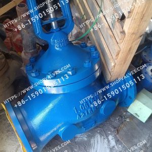
Spirax Sarco BSA3BD Bellows Sealed Globe Valve
¥40,417.00 – ¥165,213.00选择选项 本产品有多种变体。 可在产品页面上选择这些选项