
Description
Product Overview
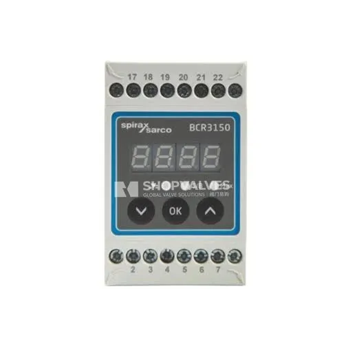
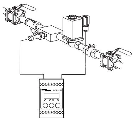
Spirax Sarco BCR3150 is an electronic blowdown controller and limit switch engineered for automated total dissolved solids (TDS) and conductivity management. Operating in steam boilers, pressurised hot water installations, and condensate recovery lines, the controller opens and closes blowdown valves to maintain optimum boiler water chemistry and prevent contaminated condensate from returning to feedtanks.
Working in conjunction with conductivity probes CP10, CP30, CP40, CP32, or CP42, the unit measures boiler water conductivity and executes automated surface blowdown whenever dissolved solids exceed the target setpoint. It also supports an external or integrated Pt100 temperature sensor (0 °C to 250 °C) to provide continuous temperature compensation under varying steam pressures.
Key Features
- Continuous TDS and conductivity limit control with CP10, CP30/CP40, or CP32/CP42 probes.
- Temperature compensation across 0 °C to 250 °C using a separate Pt100 (TP20) sensor or integrated CP32/CP42 sensor.
- Manual electronic probe cleaning cycle of 40 seconds duration (20 s cleaning current, 20 s rest) to remove scale from probe tips.
- Three configurable blowdown control modes: ON/OFF without purge, ON/OFF with purge, and ON/OFF with purge and pulsed output.
- Selectable measurement units: electrical conductivity in μS/cm or TDS in ppm.
- Dedicated 24 Vdc standby or burner input to suppress blowdown operations and conserve treated water during low-demand or boiler standby.
- Scalable 4-20 mA analogue output (maximum load 500 Ω) for remote actual value retransmission.
- Configurable measurement filter with 8-second quick response (featuring rapid step jump-out for condensate monitoring) or 64-second damping for turbulent boiler conditions.
- Password-protected access (default code 7452 from software version S-18) preventing unauthorised configuration alterations.
- Independent volt-free change-over contact for valve actuation and floating contact for MAX conductivity alarm.
Technical Specifications
| Specification | Parameter Value |
|---|---|
| Supply Voltage | 24 Vdc ±20% (SELV required) |
| Power Consumption | 4 W |
| External Supply Fuse | 0.5 A semi-delay |
| Sensor Inputs | CP32/CP42 (5-wire), CP30/CP40 (3-wire), CP10 (2-wire with Drive+Sense bridged); Pt100 2-wire (0–250 °C); Standby/burner logic input 2-wire (24 Vdc ±20%, 10 mA) |
| Valve Control Output | 1 volt-free change-over contact, rated 8 A at 250 Vac / 30 Vdc, cos φ = 1 |
| Alarm Control Output | 1 floating open/close contact, rated 8 A at 250 Vac / 30 Vdc, cos φ = 1 |
| External Output Fuse | 2.5 A slow-blow (recommended on-site) |
| Analogue Output | 4–20 mA, maximum load 500 Ω (0 μS/cm = 4 mA, span adjustable 1–9999 μS/cm) |
| Measurement Range | 1 to 9999 μS/cm (or 1 to 5000 ppm) |
| Display Interface | 4-digit green 7-segment LED display; Red LED (MAX alarm); Amber LED (Valve open); Amber LED (Standby/Burner) |
| Local Controls | 3 push-buttons for configuration and relay testing; 4-pole DIP code switch |
| Housing Construction | Base: black polycarbonate; Front: grey polycarbonate; Clip-on mounting for TH 35 rail (EN 60715) |
| Protection Rating | Housing: IP40 to EN 60529; Terminal strip: IP20 to EN 60529 |
| Electrical Safety | Pollution degree 2, for control cabinet mounting (IP54 enclosure required), fully insulated |
| Terminal Capacity | 1 x 4.0 mm² solid wire, 1 x 2.5 mm² stranded wire with ferrule, or 2 x 1.5 mm² stranded wire with ferrule |
| Weight | Approximately 0.2 kg |
| Operating Ambient Temp. | Start-up: 0 °C to 55 °C; Continuous operation: -10 °C to 55 °C |
| Storage / Transport Temp. | Storage: -20 °C to +70 °C; Transport: -20 °C to +80 °C (<100 h; 24 h defrosting period required) |
| Ambient Humidity | Maximum 95% RH, non-condensing |
| Approvals & Standards | VdTÜV Bulletin “Wasserüberwachung 100” (TÜV · WR · XX-XXX / TÜV · WÜL · XX-XXX), 2014/35/EU (LVD), 2014/30/EU (EMC) |
Applications
- Industrial and commercial steam boilers requiring automatic surface TDS control.
- Pressurised hot-water installations needing dissolved solids limit monitoring.
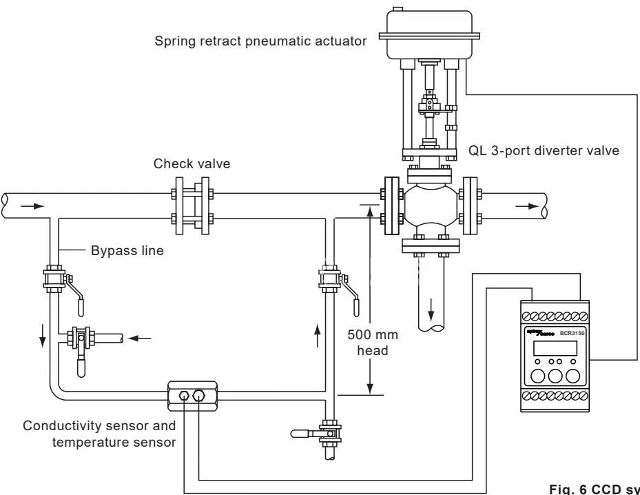
- Condensate contamination detection systems (CCD) diverting impure condensate from the boiler feedtank.
- Boiler feedtanks and condensate return monitoring tanks.
Mechanical Installation and Dimensions
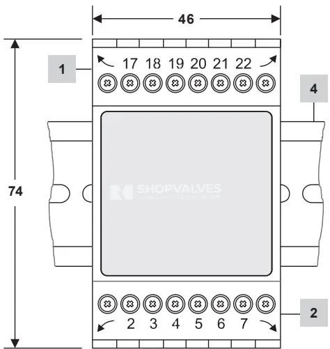
Spirax Sarco BCR3150 mounts inside control cabinets on a standard TH 35 support rail complying with EN 60715. For door installations, an optional BHC Panel Adaptor Small is available. The cabinet must maintain at least IP54 protection to comply with the unit’s electrical safety classification.
Electrical Installation and Wiring
All electrical connections are made via plug-in screw terminal strips located at the top and bottom of the housing. Signal and sensor cables must be kept strictly segregated from AC power wiring to prevent electrical noise interference.
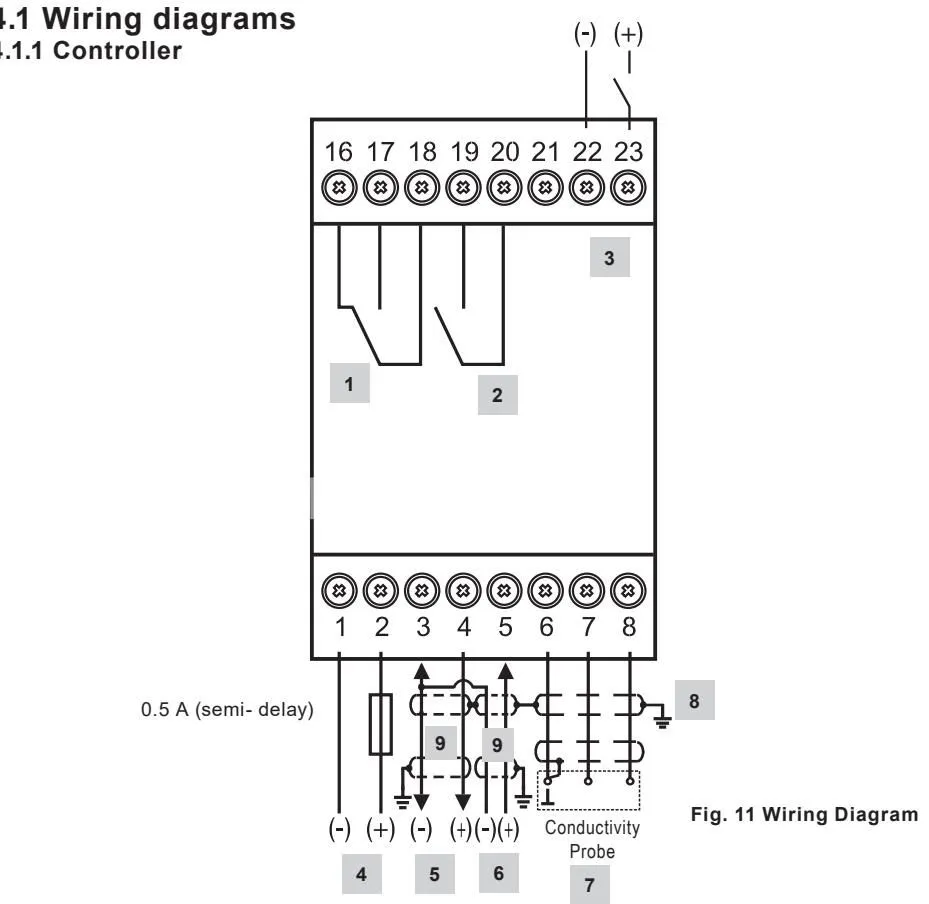
Terminal Assignments
- Terminals 16, 17, 18: Output contacts for blowdown valve actuation (17/18 closed when energised).
- Terminals 19, 20: Floating MAX alarm contacts (19/20 open when in alarm condition).
- Terminals 22, 23: Standby or burner 24 Vdc logic input.
- Terminals 25, 26: 24 Vdc supply input (Terminal 25: +24 Vdc, Terminal 26: 0 V).
- Terminals 28, 29: 4–20 mA analogue retransmission output.
- Terminals 31, 32: 2-wire Pt100 temperature sensor input.
- Terminals 34, 35, 36: Conductivity probe measuring terminals (Drive, Sense, Earth).
Code Switch Settings (Code Switch C)
The internal 4-pole code switch C configures core hardware functions:
| Pole | Setting OFF | Setting ON |
|---|---|---|
| S1 | Not used (factory default) | Not used |
| S2 | Terminals 22/23 = Standby function (default) | Terminals 22/23 = Burner function (cumulative purge) |
| S3 | Not used | ON/OFF control mode (default) |
| S4 | Electrical conductivity measured in μS/cm (default) | Electrical conductivity measured in ppm |
Operating Modes and Parameters
- ON/OFF Control Without Purge: For probes mounted directly in the boiler shell. The probe continuously measures boiler water conductivity. When conductivity exceeds setpoint SP, the blowdown valve opens until conductivity falls below the hysteresis value.
- ON/OFF Control With Purge: For probes mounted in the external blowdown line. A periodic purge (fixed 30-minute interval) opens the valve for a set duration (1 to 180 seconds) to flush stagnant water and bring representative boiler water across the probe at boiler temperature.
- ON/OFF Control With Purge and Pulsed Output: For small boilers where full blowdown capacity would rapidly draw down the water line. The valve pulses open for 10 seconds and closed for 20 seconds during blowdown, preventing low-water safety lockouts.
Parameter Menu Reference
| Code | Parameter | Adjustment Range |
|---|---|---|
| SP | Conductivity Setpoint | 1 to 9999 μS/cm (1 to 5000 ppm) |
| HYSt | Setpoint Switching Hysteresis | 0 to 3000 μS/cm (0 to 1500 ppm) |
| AL | MAX Alarm Switchpoint | 1 to 9999 μS/cm (1 to 5000 ppm) |
| CAL | Probe Calibration Value | 1 to 9999 μS/cm (1 to 5000 ppm) |
| PF | Probe Factor | 0.005 to 5 (calculated automatically) |
| Pur | Purge Duration | 0 to 180 seconds (0 = purge disabled) |
| PuL | Pulsed Output Mode | ON or OFF |
| Prob | Probe Selection | CP10, CP30, CP32, CP40, CP42 |
| FiLt | Measurement Filter | OFF (8 s response) or ON (64 s damping) |
| tC | Temperature Compensation | ON or OFF |
| tEMP | Measured Temperature | Displayed in °C (only active when tC = ON) |
| CLn | Manual Cleaning Routine | 40-second automated cleaning sequence |
| rEt | 4-20 mA Retransmit Range | 1 to 9999 μS/cm (1 to 5000 ppm) |
| tSt.o | Valve Relay Test | Energises valve relay for 60 seconds |
| tSt.A | Alarm Relay Test | De-energises alarm relay for 6 seconds |
Diagnostic Codes and Troubleshooting
Whenever a system error occurs, the MAX alarm relay trips open and the front display indicates an alphanumeric diagnostic code:
| Code | Description | Corrective Action |
|---|---|---|
| E.001 | Temperature sensor defective (reading too low) | Inspect Pt100 wiring for open circuit; test sensor resistance; replace if necessary. |
| E.002 | Temperature sensor defective (reading too high) | Inspect Pt100 wiring for short circuit; verify sensor rating; replace if damaged. |
| E.005 | Conductivity probe open circuit | Check probe cabling, cable screens, and terminal strip contacts; verify electrode integrity. |
| E.006 | Conductivity probe short circuit | Check probe insulation, wiring terminals, and electrode chamber for conductive bridging. |
| E.097 | Walkthrough test error | Perform power cycle; replace unit if internal test error recurs persistently. |
| E.098 | Walkthrough application error | Verify configuration settings and code switch positions; reset parameters. |
| E.099 | Internal controller hardware error | Internal self-test failed; replace controller if fault persists after restart. |