
Description
Product Overview
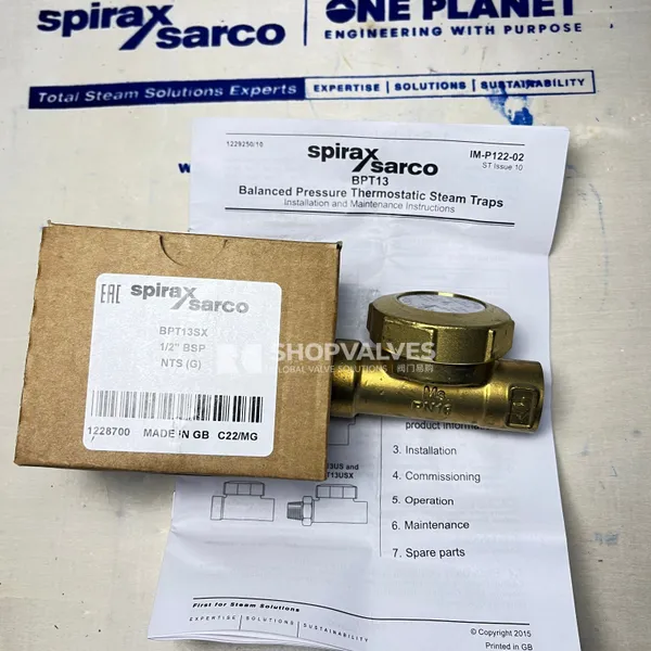
Spirax Sarco BPT13S is a straight connection balanced pressure thermostatic steam trap manufactured with a brass body. Process piping and steam tracing lines utilize this trap to discharge condensate near steam saturation temperature while removing startup air from the system. The straight piping configuration allows in-line mounting without re-routing existing pipelines.
The internal element consists of a sealed stainless steel capsule containing an evaporating fill liquid. Under cold startup conditions, the capsule remains relaxed and the valve stays wide open to vent air unrestricted. As condensate enters and reaches boiling temperature relative to system pressure, the fill liquid boils, expanding the capsule against the valve seat to close the trap. Internal cooling condenses the fill vapor, contracting the capsule and reopening the discharge port.
Key Features
- Straight-line piping connection configuration for inline installation without pipe redirection (available as BPT13S, BPT13SX, BPT13US, and BPT13USX).
- Fully maintainable design allowing in-line servicing of the capsule, seat, and strainer screen without removing the body from the pipeline.
- Stainless steel balanced pressure capsule element providing unrestricted air venting on cold start-up.
- Optional integrated cylindrical stainless steel strainer screen (SX and USX variants) to prevent particulate fouling.
- Optional union inlet connection (US and USX variants) with brass union nut and tailpiece for simplified piping breakdown.
- Three capsule fill options: standard STD (12 °C sub-cooling), sub-cooled SUB (24 °C sub-cooling), and near-to-steam NTS (4 °C sub-cooling).
- Pressure equipment compliance under European Directive 2014/68/EU within category SEP for Group 2 gases and liquids.
Technical Specifications
Pressure and Temperature Limits (ISO 6552)
| Parameter | Metric Value | Imperial Value |
|---|---|---|
| Body design conditions | PN16 | PN16 |
| Maximum allowable pressure (PMA) | 16 bar g @ 120 °C | 232 psi g @ 248 °F |
| Maximum allowable temperature (TMA) | 250 °C @ 7 bar g | 482 °F @ 102 psi g |
| Minimum allowable temperature | -20 °C | -4 °F |
| Maximum operating pressure (PMO) | 13 bar g @ 220 °C | 189 psi g @ 428 °F |
| Maximum operating temperature (TMO) | 250 °C @ 7 bar g | 482 °F @ 102 psi g |
| Minimum operating temperature | 0 °C | 32 °F |
| Maximum cold hydraulic test pressure | 24 bar g | 348 psi g |
Dimensions and Weights

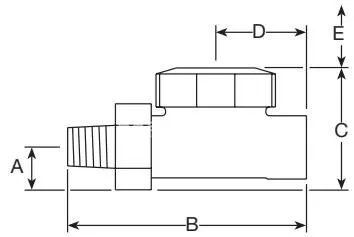
| Type | Size | A (mm) | B (mm) | C (mm) | D (mm) | E Withdrawal (mm) | Weight (kg) |
|---|---|---|---|---|---|---|---|
| BPT13S | ½” | 14 | 76 | 47 | 38 | 55 | 0.45 |
| BPT13S | ¾” | 20 | 80 | 53 | 40 | 55 | 0.50 |
| BPT13US | ½” | 19 | 105 | 52 | 38 | 55 | 0.55 |
| BPT13US | ¾” | 22 | 115 | 57 | 40 | 55 | 0.60 |
Note: Screwed connections are available in ⅜”, ½”, and ¾” BSP (BS 21 / ISO 7-1 Rp) or NPT.
Applications
- Steam mains drainage along horizontal straight pipe runs.
- Equipment air venting during plant startup operations.
- Hospital sterilisers and wet steaming ovens (when specified with the NTS capsule fill).
- Vacuum return systems (when specified with the SUB sub-cooled capsule fill).
Straight Connection Model Configurations
| Model | Connection Style | Internal Strainer Screen | Inlet Fitting |
|---|---|---|---|
| BPT13S | Straight screwed connections | No | Standard screwed body |
| BPT13SX | Straight screwed connections | Yes (ASTM A240 316L) | Standard screwed body |
| BPT13US | Straight connections | No | Union inlet with brass nut and tailpiece |
| BPT13USX | Straight connections | Yes (ASTM A240 316L) | Union inlet with brass nut and tailpiece |
Capsule Fill Options
| Capsule Code | Operating Sub-Cooling | Application Characteristics |
|---|---|---|
| STD | ~12 °C (53 °F) below saturation | Standard condensate discharge for mains and tracers |
| SUB | ~24 °C (75 °F) below saturation | Sub-cooled operation, suitable for vacuum return systems |
| NTS | ~4 °C (7 °F) below saturation | Near-to-steam operation for critical sterilisers and wet steaming ovens |
Materials of Construction
| Item No. | Part Name | Material | Specification Standard |
|---|---|---|---|
| 1 | Body | Brass | BS EN 12165 CW 617N |
| 2 | Cap | Brass | BS EN 12165 CW 617N |
| 3 | ‘O’ ring | Synthetic rubber fluorocarbon | High fluorine fluorocarbon |
| 4 | Capsule | Stainless steel | Standard grade |
| 5 | Spring | Stainless steel | BS 2056 302 S26 |
| 6 | Spacer plate | Stainless steel | BS 1449 304 S16 |
| 7 | Valve seat | Stainless steel | BS 970 431 S29 |
| 8 | Valve seat gasket | Stainless steel | BS 1449 304 S11 |
| 9 | Strainer screen (SX / USX) | Stainless steel | ASTM A240 316L |
| 10 | Union nut and tailpiece (US / USX) | Brass | BS EN 12165 CW 617N |
Installation and Maintenance
Installation Guidelines
- Install the trap with the capsule in a horizontal plane and the cap oriented at the top.
- Employ a cooling leg / drop leg upstream of the trap to prevent cooling condensate from accumulating in the steam main.
- Maintain a minimum withdrawal clearance of 55 mm above the cap to permit in-line disassembly.
- When discharging to atmosphere, fit a diffuser on the outlet to reduce discharge velocity, erosion, and noise.
- Install upstream and downstream isolation valves to permit safe maintenance.
Maintenance and Assembly Torques
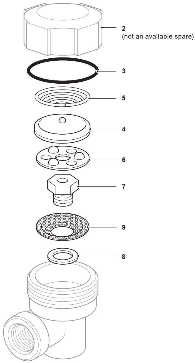
- Remove the cap (2) using a 50 mm A/F spanner.
- Remove the spring (5), capsule (4), and spacer plate (6), then unscrew the valve seat (7) using a 17 mm A/F spanner.
- On BPT13SX and BPT13USX, extract the cylindrical strainer screen (9) and seat gasket (8) for cleaning or replacement.
- Reassemble with a new seat gasket (8) and apply anti-seize compound to the valve seat threads.
- Install the conical spring (5) with its narrow end oriented downwards against the capsule (4).
- Early spacer plates are unidirectional and must be positioned with the highest points uppermost; modern spacer plates fit either way up.
| Item | Part | Tool / Width Across Flats | Tightening Torque (N m) | Tightening Torque (lbf ft) |
|---|---|---|---|---|
| 2 | Cap (‘O’ ring seal) | 50 mm A/F | 50 – 60 | 37 – 44 |
| 2 | Cap (Gasket seal, earlier models) | 50 mm A/F | 90 – 110 | 66 – 81 |
| 7 | Valve seat | 17 mm A/F | 35 – 40 | 26 – 29 |