
Description
Product Overview
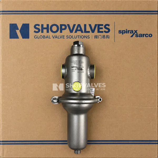
Spirax Sarco SRV461 is a direct acting pressure reducing valve constructed entirely with stainless steel wetted components for steam, liquid, and gas distribution lines. It regulates downstream process pressure autonomously, eliminating the need for external power supplies or pneumatic actuators across hygienic and critical utility services.
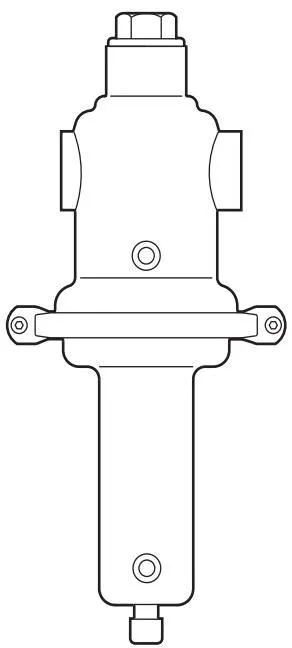
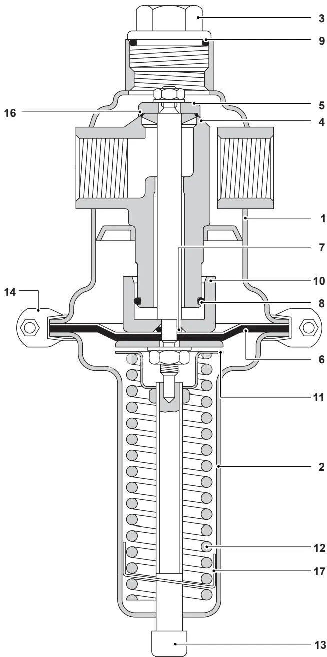
Prior to operation, the internal control spring applies downward force on the spindle to hold the valve head in the open position. When the process fluid flows through the seat, rising downstream pressure is transmitted back through an external 1/4” sensing pipe onto the upper surface of the diaphragm, opposing the control spring. Once downstream pressure matches the selected set point, forces on the diaphragm balance the spring load and the valve head modulates to maintain stable pressure. Downstream pressure increases drive the diaphragm upward to close the valve orifice, whereas downstream pressure drops allow the spring to reopen the valve.
Key Features
- All wetted components constructed from AISI 316L (1.4404), 1.4408, 1.4462, and AISI 316Ti (1.4571) stainless steel grades.
- Screwed line connections in sizes 1/2”, 3/4”, 1”, 1 1/4”, 1 1/2”, and 2” with BSP or NPT threading.
- Fluoraz (FEPM) soft seat sealing as standard, with optional Viton/FPM elastomers available for hydrocarbon media.
- Two-layer diaphragm design incorporating a protective fluid-facing PTFE layer over an elastomeric core.
- PN40 body pressure rating withstanding up to 60 bar g cold hydraulic proof testing.
- Food+ variants certified to (EC) 1935:2004, (EC) 2023:2006, (EU) 10/2011, and FDA Title 21 CFR requirements.
- High shut-off tightness with seat leakage certified to 0.05% or less of maximum Kv capacity.
Technical Specifications
| Parameter | Specification Details |
|---|---|
| Body Design Rating | PN40 |
| Pipe Connections | Screwed BSP or Screwed NPT |
| Nominal Sizes | 1/2”, 3/4”, 1”, 1 1/4”, 1 1/2”, 2” (DN15 to DN50 equivalent) |
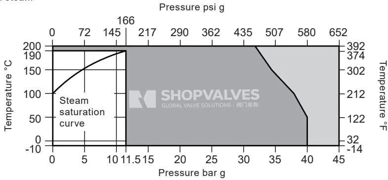
| Maximum Allowable Pressure | 40 bar g @ 50 °C (580 psi g @ 122 °F) / 38 bar g @ 38 °C |
| Maximum Allowable Temperature | 200 °C @ 31.8 bar g (392 °F @ 461 psi g) / 300 °C @ 23.2 bar g |
| Minimum Allowable Temperature | -10 °C (14 °F) |
| Maximum Operating Pressure (Saturated Steam) | 11.5 bar g @ 190 °C (167 psi g @ 374 °F) |
| Maximum Operating Pressure (Liquids and Gases) | 40 bar g @ 50 °C (580 psi g @ 122 °F) |
| Maximum Operating Temperature (Saturated Steam) | 190 °C @ 11.5 bar g (374 °F @ 167 psi g) |
| Maximum Operating Temperature (Liquids and Gases) | 50 °C @ 40 bar g (122 °F @ 580 psi g) / 130 °C @ 12 bar g |
| Minimum Operating Temperature | -10 °C (14 °F) |
| Hydraulic Test Pressure (Cold) | 60 bar g (870 psi g) |
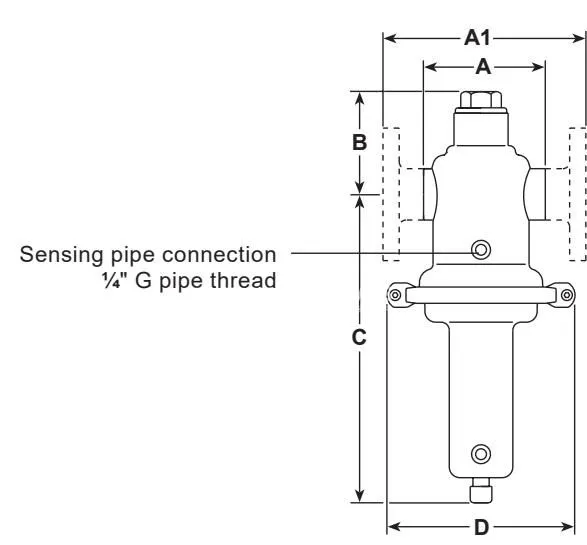
| Pressure Sensing Port | 1/4” G female thread |
| Seat Leakage Rate | <= 0.05% of maximum Kv value |
Downstream Set Pressure Ranges
| Pressure Range (bar g) | Pressure Range (psi g) |
|---|---|
| 0.02 - 0.12 bar g | 0.29 - 1.74 psi g |
| 0.10 - 0.50 bar g | 1.45 - 7.25 psi g |
| 0.30 - 1.10 bar g | 4.35 - 15.95 psi g |
| 0.80 - 2.50 bar g | 11.60 - 36.25 psi g |
| 2.00 - 5.00 bar g | 29.00 - 72.50 psi g |
| 4.00 - 8.00 bar g | 58.00 - 116.00 psi g |
| 6.00 - 12.00 bar g | 87.00 - 174.00 psi g |
Flow Coefficients (Kv Values)
| Valve Size | 1/2” | 3/4” | 1” | 1 1/4” | 1 1/2” | 2” |
|---|---|---|---|---|---|---|
| Kv at 20% offset | 4.0 | 5.6 | 6.4 | 17.6 | 17.6 | 17.6 |
| Maximum Kv | 5.0 | 7.0 | 8.0 | 22.0 | 22.0 | 22.0 |
Note: Use Kv values at 20% offset to calculate sizing under variable operating conditions. Use maximum Kv values for safety valve sizing.
Permissible Reduction Ratios (Maximum P1 / P2)
| Setting Range (bar g) | Nominal Size: 1/2” - 1” | Nominal Size: 1 1/4” - 2” |
|---|---|---|
| 0.02 - 0.12 bar g | 80:1 | 50:1 |
| 0.10 - 0.50 bar g | 40:1 | 25:1 |
| 0.30 - 1.10 bar g | 30:1 | 18:1 |
| 0.80 - 12.00 bar g | 20:1 | 12:1 |
Dimensions and Weights (Screwed Connections)
| Size | Face-to-Face A (mm) | Center-to-Bottom B (mm) |
|---|---|---|
| 1/2” | 85 | 76 |
| 3/4” | 91 | 76 |
| 1” | 85 | 76 |
| 1 1/4” | 130 | 90 |
| 1 1/2” | 145 | 90 |
| 2” | 185 | 90 |
| Set Pressure Range (bar g) | Height C (mm) | Diaphragm Diameter ØD (mm) |
|---|---|---|
| 0.02 - 0.12 | 300 | 360 |
| 0.1 - 0.5 | 300 | 264 |
| 0.3 - 1.1 | 300 | 200 |
| 0.8 - 5.0 | 235 | 138 |
| 4.0 - 12.0 | 235 | 138 |
| Nominal Size (Screwed) | Weight: 0.02 - 0.12 bar | Weight: 0.1 - 0.5 bar | Weight: 0.3 - 1.1 bar | Weight: 0.8 - 12.0 bar |
|---|---|---|---|---|
| 1/2” - 1” | 13.5 kg | 7.1 kg | 6.1 kg | 3.1 kg |
| 1 1/4” - 2” | 14.4 kg | 8.0 kg | 7.0 kg | 4.0 kg |
Applications
- Clean steam supplies in hygienic facilities
- Gas and liquid feed systems serving centrifuges
- Pharmaceutical freeze dryers and lyophilisation units
- Medical and laboratory sterilising equipment
- Commercial autoclave pressure feeds
- Process storage, mixing, and fermentation vessels
- Direct steam injection humidifiers
- Culinary steam stations for food production
Materials of Construction
| Item No. | Part Description | Material | Werkstoff No. | AISI Equivalent |
|---|---|---|---|---|
| 1 | Body | Stainless steel | 1.4404 | 316L |
| 2 | Spring housing | Stainless steel | 1.4404 | 316L |
| 3 | Cap | Stainless steel | 1.4571 | 316Ti |
| 4 | Valve seat | Stainless steel | 1.4404 | 316L |
| 5 | Valve | Stainless steel | 1.4404 | 316L |
| 6 | Diaphragm | EPDM/PTFE composite | - | - |
| 7 | ‘O’ ring | FEPM (Fluoraz) or EPDM | - | - |
| 8 | ‘O’ ring | FEPM (Fluoraz) or EPDM | - | - |
| 9 | ‘O’ ring | FEPM (Fluoraz) or EPDM | - | - |
| 10 | Piston | Stainless steel | 1.4571 | 316Ti |
| 11 | Top spring plate | Stainless steel | 1.4571 | 316Ti |
| 12 | Spring | Stainless steel | 1.4310 | 301 (nearest) |
| 13 | Adjustment screw | Stainless steel | 1.4404 | 316L |
| 14 | V-band clamp | Stainless steel | AISI 300 series | - |
| 16 | Soft seal | Fluoraz (FEPM) or FPM | - | - |
| 17 | Spring clip | Stainless steel | 1.4301 | 304 |
Installation and Commissioning
Fit the valve strictly into horizontal pipeline sections. When configured for steam duty, install the valve with the spring adjustment housing positioned downwards below the pipeline center line to ensure condensate collects within the diaphragm chamber rather than exposing internal elastomeric seals to live superheated vapors.
Pipeline Ancillaries and Layout Guidelines
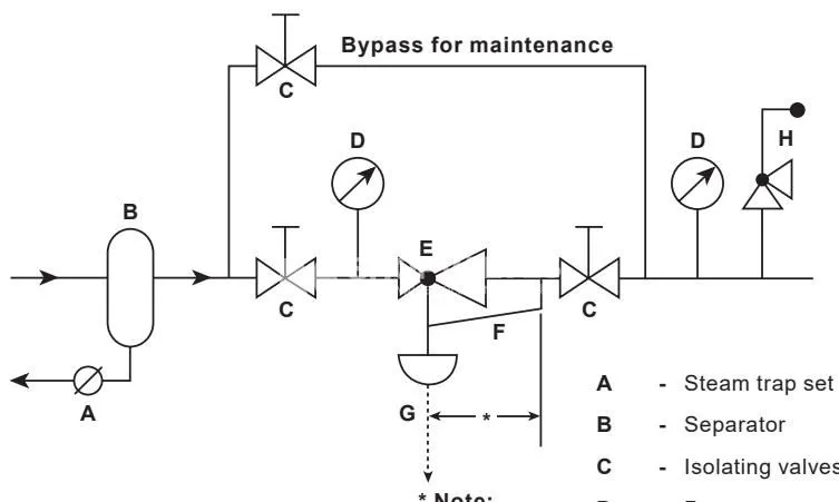
- Maintain straight pipe lengths of at least 10 pipe diameters upstream and downstream before any isolation valves.
- Prevent pipeline mechanical stresses caused by thermal expansion or unsupported piping runs from transferring onto the valve body.
- Fit an upstream pipeline strainer mounted horizontally on its side to avoid liquid pooling that restricts free mesh area.
- Protect steam installations by draining the upstream main using a collection pocket or steam separator paired with a steam trap unit.
- Size piping generously to eliminate line drops, using eccentric reducers when transitioning pipe diameters.
- Connect a 1/4” sensing line with compression fittings onto a straight downstream run at least 15 pipe diameters away from the valve and at least 10 pipe diameters clear of fittings. Pitch the line upward toward the main pipe on steam applications. Incorporate an isolating valve on the sensing pipe for servicing, and install a damping pot whenever downstream set pressure is below 0.1 bar g.
Commissioning Steps
- Verify all line isolation valves are fully closed.
- Turn the adjustment screw counter-clockwise until tension on the control spring is completely released.
- Open the steam trap isolation valve ahead of the reducing station to discharge residual condensate.
- Open the isolating valve fitted on the 1/4” pressure sensing line.
- Open the downstream pipeline isolation valve.
- Slowly open the main upstream inlet stop valve to prevent waterhammer shock.
- Rotate the spring adjustment screw clockwise until the target pressure reading registers on the downstream gauge. Readjust after thermal equilibrium is reached.
Maintenance and Spare Parts
Release all control spring compression before attempting disassembly. Disconnecting the V-band clamp while the spring remains compressed presents an immediate ejection hazard.
For valves containing Viton/FPM seals, verify the assembly has not been exposed to temperatures near 315 °C (599 °F), which causes thermal decomposition into hydrofluoric acid. On Food+ models, execute a CIP (cleaning in place) sanitation cycle before returning serviced valves to service.
Available Spare Parts
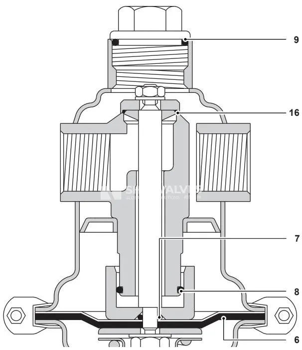
| Spare Kit Description | Component Number Indicators |
|---|---|
| Diaphragm and ‘O’ Ring Kit | 6 (Diaphragm), 7 (‘O’ ring), 8 (‘O’ ring), 9 (‘O’ ring), 16 (Seat soft seal) |
When ordering replacement kits, specify the product size (1/2” to 2”), model designation SRV461S, pressure range rating, elastomer material (FEPM standard, or FPM), and whether Food+ certification applies.