
Description
Product Overview
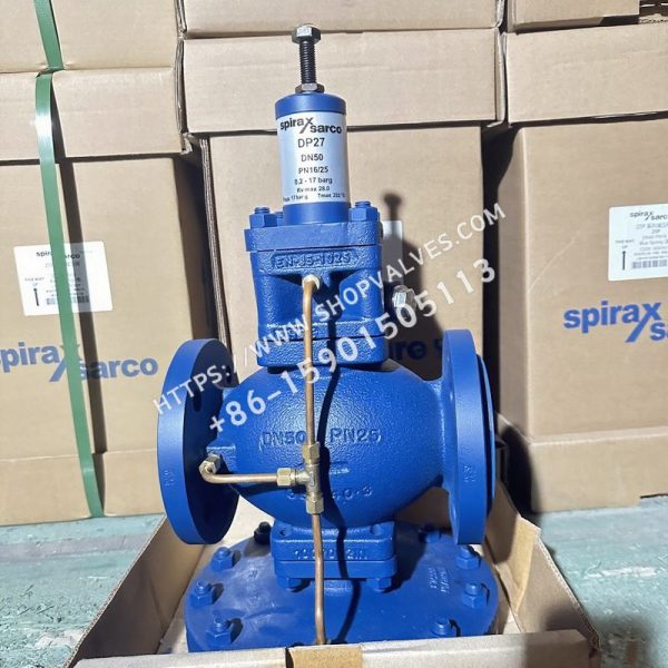
Spirax Sarco DP27 Flanged is a pilot operated pressure reducing valve manufactured with an SG iron body (DIN 1693 GGG 40.3 / EN JS 1025) designed specifically for flanged piping systems. This configuration isolates downstream industrial networks from fluctuating upstream pressures across steam, compressed air, and inert industrial gas lines. The flanged body design accommodates high pipe-load environments and supports standard flange drilling options from DN15LC up to DN50, eliminating screwed joint leakage in critical distribution mains. For compact small-bore installations from DN15LC to DN25, a screwed DP27 variant is also available.
Key Features
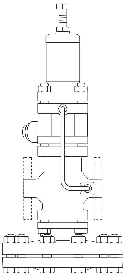
- Standard pipeline flanging conforming to EN 1092 PN16 and PN25 across DN15 to DN50, plus BS 10 Table H and ASME 300 across DN25 to DN50.
- Optional flange executions available on request including ASME 150 (DN15–DN50), JIS 10/16 (DN15–DN50), BS 10 Table F (DN15–DN20), and ASME 300 (DN15).
- Low Capacity flanged variant (DN15LC) engineered with a 1.0 Kv rating for lower steam loads without body resizing.
- Full compatibility across derivative variants including DP27E solenoid shut-off, DP27G/GY soft-seated gas service, DP27R remote air-set, and DP27Y low-pressure sterilizer units.
- Pressure containment certified under PN25 design conditions with cold hydraulic test pressure up to 38 bar g without internals and 25 bar g with internals fitted.
Technical Specifications
| Specification Parameter | Technical Data |
|---|---|
| Body Material | SG iron DIN 1693 GGG 40.3 / EN JS 1025 |
| Nominal Flange Sizes | DN15LC, DN15, DN20, DN25, DN32, DN40, DN50 |
| Standard Flange Connections | EN 1092 PN16 and PN25 (DN15–DN50); BS 10 Table H and ASME 300 (DN25–DN50) |
| Flanges Available on Request | ASME 150 (DN15–DN50); JIS 10/16 (DN15–DN50); BS 10 Table F (DN15–DN20); ASME 300 (DN15) |
| Body Design Rating | PN25 |
| Maximum Design Pressure (Curve A-D-E) | 25 bar g @ 120 °C (EN 1092 PN25, ASME 300, BS 10 Table H) |
| Maximum Design Pressure (Curve A-B-C) | 17.2 bar g @ 40 °C (ASME 150) |
| Maximum Design Temperature | 232 °C @ 21 bar g |
| Minimum Design Temperature | -10 °C |
| Max. Upstream Pressure (Saturated Steam) | 17 bar g (DP27, DP27R, DP27Y); 10 bar g (DP27E) |
| Max. Upstream Pressure (Air / Inert Gas) | 25 bar g (DP27G, DP27GY) |
| Maximum Operating Temperature | 232 °C @ 21 bar g (DP27, DP27Y); 190 °C @ 10 bar g (DP27E); 120 °C @ 25 bar g (DP27G, DP27GY) |
| Minimum Operating Temperature | 0 °C |
| Maximum Differential Pressure | 17 bar (DP27, DP27R, DP27Y); 25 bar g (DP27G, DP27GY); 10 bar (DP27E) |
| Cold Hydraulic Shell Test Pressure | 38 bar g (without internals); 25 bar g (internals fitted) |
| Flow Capacity ($K_v$ full capacities) | DN15LC: 1.0; DN15: 2.8; DN20: 5.5; DN25: 8.1; DN32: 12.0; DN40: 17.0; DN50: 28.0 |
Applications
- Industrial steam distribution manifolds and boiler headers requiring bolted EN 1092 or ASME flanged pipe joints.
- Autoclaves, hospital sterilizers, and low-pressure processing machinery utilizing DP27Y flanged assemblies with 0.2 to 3.0 bar g control spring ranges.
- Compressed air and inert industrial gas distribution lines using DP27G or DP27GY soft-seal flanged valves.
- Remote electrical shut-off stations requiring DP27E flanged valves with integral solenoid control.
- Pneumatically modulated steam networks utilizing DP27R flanged valves controlled by instrument air regulator signals.
Flange Dimensions and Weights
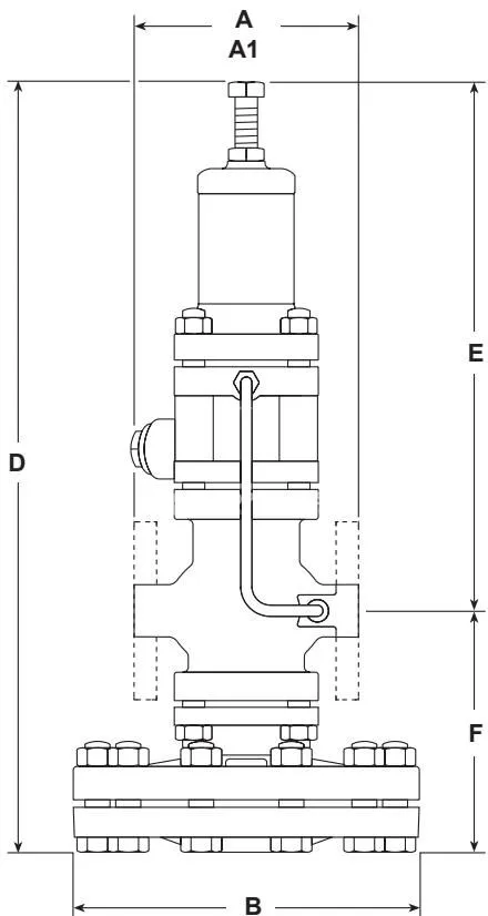
DP27, DP27E and DP27Y Flanged Dimensions (mm) and Weights (kg)
| Size | Face-to-Face A1 (BS 10 H) | Face-to-Face A1 (PN16/25) | Face-to-Face A1 (ASME 300) | Face-to-Face A1 (BS 10 F) | Face-to-Face A1 (ASME 150) | Face-to-Face A1 (JIS 10/16) | Width B | Height D | Centre E | Drop F | Flanged Weight (kg) |
|---|---|---|---|---|---|---|---|---|---|---|---|
| DN15LC | - | 130 | 126.6 | 117 | 120.2 | 122 | 185 | 406 | 276 | 130 | 14.0 |
| DN15 | - | 130 | 126.6 | 117 | 120.2 | 122 | 185 | 406 | 276 | 130 | 14.0 |
| DN20 | - | 150 | - | 133 | 139.4 | 142 | 185 | 406 | 276 | 130 | 14.9 |
| DN25 | 160 | 160 | 160.0 | - | 160.0 | 152 | 207 | 430 | 282 | 148 | 17.2 |
| DN32 | 180 | 180 | 180.0 | - | 176.0 | 176 | 207 | 430 | 282 | 148 | 18.2 |
| DN40 | 200 | 200 | 200.0 | - | 199.0 | 196 | 255 | 475 | 297 | 178 | 30.2 |
| DN50 | 230 | 230 | 230.0 | - | 228.0 | 222 | 255 | 475 | 297 | 178 | 32.2 |
DP27G and DP27GY Flanged Dimensions (mm) and Weights (kg)
| Size | Face-to-Face A1 (BS 10 H) | Face-to-Face A1 (PN16/25) | Face-to-Face A1 (ASME 300) | Face-to-Face A1 (BS 10 F) | Face-to-Face A1 (ASME 150) | Face-to-Face A1 (JIS 10/16) | Width B | Height D | Centre E | Drop F | Flanged Weight (kg) |
|---|---|---|---|---|---|---|---|---|---|---|---|
| DN15 | - | 130 | 126.6 | 117 | 120.2 | 122 | 185 | 364 | 234 | 130 | 12.8 |
| DN20 | - | 150 | - | 133 | 139.4 | 142 | 185 | 364 | 234 | 130 | 13.7 |
| DN25 | 160 | 160 | 160.0 | - | 160.0 | 152 | 207 | 388 | 240 | 148 | 16.0 |
| DN32 | 180 | 180 | 180.0 | - | 176.0 | 176 | 207 | 388 | 240 | 148 | 17.0 |
| DN40 | 200 | 200 | 200.0 | - | 199.0 | 196 | 255 | 433 | 255 | 178 | 29.0 |
| DN50 | 230 | 230 | 230.0 | - | 228.0 | 222 | 255 | 433 | 255 | 178 | 31.5 |
DP27R Flanged Dimensions (mm) and Weights (kg)
| Size | Face-to-Face A1 (BS 10 H) | Face-to-Face A1 (PN16/25) | Face-to-Face A1 (ASME 300) | Face-to-Face A1 (BS 10 F) | Face-to-Face A1 (ASME 150) | Face-to-Face A1 (JIS 10/16) | Width B | Height D | Centre E | Drop F | Flanged Weight (kg) |
|---|---|---|---|---|---|---|---|---|---|---|---|
| DN15LC | - | 130 | 126.6 | 117 | 120.2 | 122 | 185 | 296 | 166 | 130 | 13.0 |
| DN15 | - | 130 | 126.6 | 117 | 120.2 | 122 | 185 | 296 | 166 | 130 | 13.0 |
| DN20 | - | 150 | - | 133 | 139.4 | 142 | 185 | 296 | 166 | 130 | 13.9 |
| DN25 | 160 | 160 | 160.0 | - | 160.0 | 152 | 207 | 320 | 172 | 148 | 16.2 |
| DN32 | 180 | 180 | 180.0 | - | 176.0 | 176 | 207 | 320 | 172 | 148 | 16.2 |
| DN40 | 200 | 200 | 200.0 | - | 199.0 | 196 | 255 | 364 | 186 | 178 | 29.2 |
| DN50 | 230 | 230 | 230.0 | - | 228.0 | 222 | 255 | 364 | 186 | 178 | 31.7 |
Pressure and Temperature Operating Envelopes
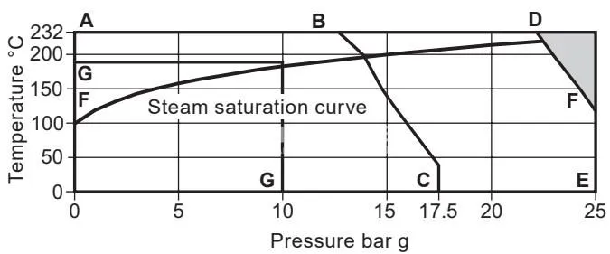
Operating limits depend directly on the selected flange standard:
- Curve A-D-E: Applies to flanged EN 1092 PN25, ASME 300, and BS 10 Table H connections. The maximum allowable pressure is 25 bar g at temperatures up to 120 °C, reducing to 21 bar g at 232 °C.
- Curve A-B-C: Applies to ASME 150 flanged connections. The maximum pressure is limited to 17.2 bar g at 40 °C, de-rating along curve A-B-C across elevated temperatures.
- Sub-model Limitations: DP27E flanged units are capped at 10 bar g at 190 °C (curve G-G). DP27G and DP27GY flanged units are restricted to a maximum operating temperature of 120 °C at 25 bar g (curve F-F-E).
Flanged Body Hardware and Fasteners
Maintenance and assembly of the flanged DP27 body require specific fasteners and torques based on valve size:
- Main Body Studs and Nuts (Item 25): Steel studs (BS 4439 Gr. 8.8) and nuts (BS 3692 Gr. 8). DN15 to DN32 utilize M10 x 25 mm studs; DN40 and DN50 utilize M12 x 30 mm studs.
- Spring Housing / Cover Studs (Item 7): DN15 to DN32 use M10 x 95 mm studs tightened to 40 - 50 N m. DN40 and DN50 use M12 x 95 mm studs tightened to 45 - 55 N m.
- Main Diaphragm Chamber Bolts (Item 28): DN15 to DN32 require a set of 10 off M12 x 50 mm bolts; DN40 and DN50 require a set of 12 off M12 x 55 mm bolts. Tightening torque is 80 - 100 N m (75 N m during reassembly).
- Main Valve Seat Tightening Torques: DN15LC and DN15 (30 mm A/F external): 110 - 120 N m; DN20 (36 mm A/F external): 140 - 150 N m; DN25 (19 mm A/F internal): 230 - 250 N m; DN32 (24 mm A/F internal): 300 - 330 N m; DN40 (30 mm A/F internal): 450 - 490 N m; DN50 (41 mm A/F internal): 620 - 680 N m.
- Internal Valve Lift Setting: DN15LC, DN15, and DN20: 2.5 mm; DN25: 3.0 mm; DN32: 3.5 mm; DN40: 4.5 mm; DN50: 5.0 mm.
Spares Interchangeability across Flanged Sizes
Spare part groups are shared across flanged sizes as identified in the manufacturer interchangeability matrix:
| Spares Item | 15LC | 15 | 20 | 25 | 32 | 40 | 50 |
|---|---|---|---|---|---|---|---|
| Maintenance kit | f | f | a | b | c | d | e |
| Main diaphragm | a | a | a | b | b | c | c |
| Pilot diaphragms | a | a | a | a | a | a | a |
| Pilot valve chamber assembly | a | a | a | a | a | b | b |
| Pilot filter element | a | a | a | a | a | a | a |
| Pilot filter cap gaskets | a | a | a | a | a | a | a |
| PTFE seals | a | a | a | a | a | a | a |
| Main valve assembly | a | b | c | d | e | f | g |
| Internal strainer screen | f | f | a | b | c | d | e |
| Main valve return spring | a | a | a | a | a | c | c |
| Pressure adjustment spring | a | a | a | a | a | a | a |
| Control pipe assembly | f | f | a | b | c | d | e |
| Balance pipe assembly | f | f | a | b | c | d | e |
| Body gasket | a | a | a | a | a | b | b |
| Spring housing studs and nuts | a | a | a | a | a | b | b |
| Main body studs and nuts | a | a | a | a | a | b | b |
| Diaphragm securing bolts and nuts | a | a | a | a | a | b | b |
| Pushrod and diaphragm plate | a | a | a | b | b | c | c |