
Description
Product Overview
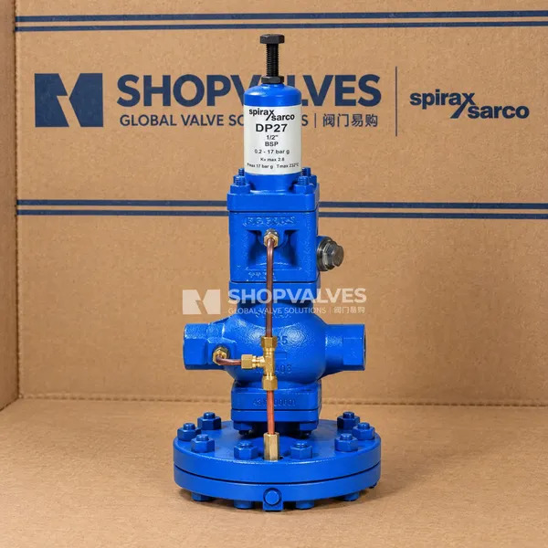
Spirax Sarco DP27 screwed pressure reducing valves are pilot operated control valves designed for direct screwed installation in steam, compressed air, and inert industrial gas distribution lines. These valves stabilize downstream delivery pressures against fluctuating upstream conditions in compact pipe layouts where flanged connections are impractical. Fabricated with SG iron (DIN 1693 GGG 40.3 / EN JS 1025) bodies, screwed DP27 configurations are manufactured in sizes DN15LC, DN15 (1/2”), DN20 (3/4”), and DN25 (1”). Connection standards comprise parallel BSP to BS 21 across all four sizes, as well as NPT threads on sizes DN15 through DN25. Sizes DN32, DN40, and DN50 are not produced with screwed connections; for these, refer to the DP27 flanged pressure-reducing valve.
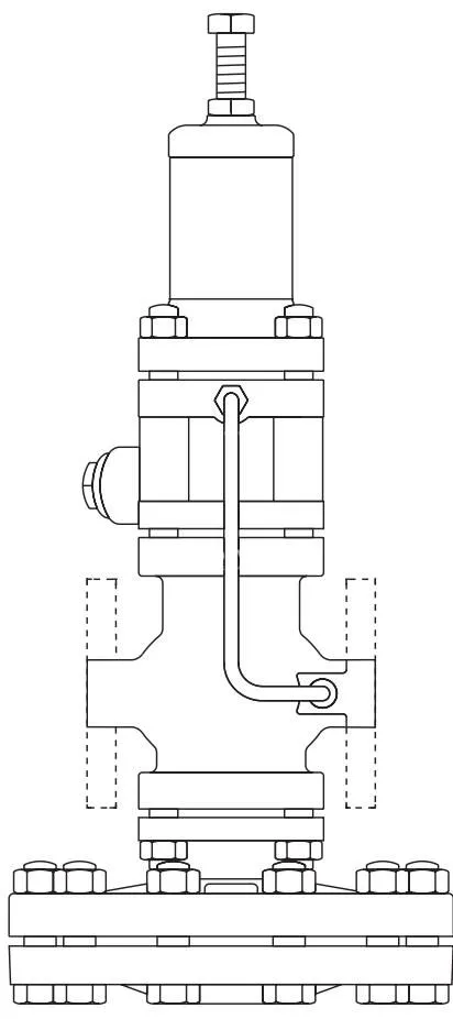
Screwed DP27 models encompass several dedicated variants sharing the identical compact screwed body footprint: standard DP27 with a conical spring spanning 0.2 to 17 bar g downstream pressure; DP27E incorporating an electric solenoid valve for remote electrical shut-off up to 10 bar g; DP27G utilizing nitrile soft seals for compressed air and inert gases up to 25 bar g upstream pressure; DP27GY combining nitrile soft seals with a low-rate spring for 0.2 to 3.0 bar g gas applications; DP27R with a pneumatic actuator chamber for remote air-pressure adjustment up to 15 bar g; and DP27Y equipped with a low-rate spring for low-pressure steam regulation between 0.2 and 3.0 bar g. DP27 screwed valves comply with the EU Pressure Equipment Directive (SEP category for DN15 to DN25) and are not suitable for oxygen service.
Key Features
- Screwed Connection Geometry: Available in BSP (BS 21 parallel) for DN15LC, DN15, DN20, and DN25, with NPT threading available for DN15, DN20, and DN25.
- Compact SG Iron Body: Spheroidal graphite cast iron body (DIN 1693 GGG 40.3) rated to PN25 design conditions with maximum cold hydraulic test pressures reaching 38 bar g without internals and 25 bar g with internals fitted.
- Wide Operational Envelope: Permissible design pressure of 25 bar g at 120 °C and maximum design temperature of 232 °C at 21 bar g, with operating limits along curve A-D-E.
- Precise Pilot Control: Internal pilot mechanism with phosphor bronze pilot diaphragms (BS 2870 PB102), stainless steel pilot plunger, stainless steel pilot seat with integral PTFE seal, and an internal brass pilot filter element.
- Flow Capacity Range: Full-capacity safety valve sizing Kv values of 1.0 for DN15LC, 2.8 for DN15, 5.5 for DN20, and 8.1 for DN25.
- Electrical and Remote Actuation Variants: Compatible with solenoid override (DP27E) or remote pneumatic signal loading (DP27R) on the same screwed body geometry.
Technical Specifications
| Specification Parameter | DN15LC Screwed | DN15 (1/2”) Screwed | DN20 (3/4”) Screwed | DN25 (1”) Screwed |
|---|---|---|---|---|
| Available Thread Types | BSP (BS 21 parallel) | BSP / NPT | BSP / NPT | BSP / NPT |
| Body Material | SG iron DIN 1693 GGG 40.3 | SG iron DIN 1693 GGG 40.3 | SG iron DIN 1693 GGG 40.3 | SG iron DIN 1693 GGG 40.3 |
| Body Design Rating | PN25 | PN25 | PN25 | PN25 |
| Maximum Design Pressure | 25 bar g @ 120 °C | 25 bar g @ 120 °C | 25 bar g @ 120 °C | 25 bar g @ 120 °C |
| Maximum Design Temperature | 232 °C @ 21 bar g | 232 °C @ 21 bar g | 232 °C @ 21 bar g | 232 °C @ 21 bar g |
| Minimum Design Temperature | -10 °C | -10 °C | -10 °C | -10 °C |
| Maximum Saturated Steam Inlet (DP27/R/Y) | 17 bar g | 17 bar g | 17 bar g | 17 bar g |
| Maximum Saturated Steam Inlet (DP27E) | 10 bar g | 10 bar g | 10 bar g | 10 bar g |
| Maximum Air/Gas Inlet (DP27G/GY) | Not Available | 25 bar g | 25 bar g | 25 bar g |
| Downstream Pressure Range (Standard) | 0.2 to 17 bar g | 0.2 to 17 bar g | 0.2 to 17 bar g | 0.2 to 17 bar g |
| Downstream Pressure Range (Y / GY) | 0.2 to 3.0 bar g | 0.2 to 3.0 bar g | 0.2 to 3.0 bar g | 0.2 to 3.0 bar g |
| Maximum Operating Temperature | 232 °C (DP27/Y/R) / 190 °C (DP27E) | 232 °C (DP27/Y/R) / 190 °C (DP27E) / 120 °C (DP27G/GY) | 232 °C (DP27/Y/R) / 190 °C (DP27E) / 120 °C (DP27G/GY) | 232 °C (DP27/Y/R) / 190 °C (DP27E) / 120 °C (DP27G/GY) |
| Minimum Operating Temperature | 0 °C | 0 °C | 0 °C | 0 °C |
| Full-Capacity Flow Coefficient (Kv) | 1.0 | 2.8 | 5.5 | 8.1 |
| Flow Coefficient Cv (UK / US) | 0.963 / 1.156 | 2.70 / 3.24 | 5.30 / 6.36 | 7.80 / 9.36 |
| Main Valve Lift | 2.5 mm | 2.5 mm | 2.5 mm | 3.0 mm |
| Hydraulic Test Pressure (Cold) | 38 bar g (bare) / 25 bar g (assembled) | 38 bar g (bare) / 25 bar g (assembled) | 38 bar g (bare) / 25 bar g (assembled) | 38 bar g (bare) / 25 bar g (assembled) |
Applications
- Saturated and superheated steam supply manifolds supplying small heat exchangers, unit heaters, and process kettles.
- Hospital autoclaves, sterilizers, and laundries requiring low-pressure steam regulation down to 0.2 bar g using the DP27Y.
- Point-of-use compressed air headers and inert industrial gas distribution lines using nitrile soft-seated DP27G or DP27GY models.
- Automated batching operations utilizing DP27E screwed valves tied to timers or interlocks for electrical fail-safe isolation.
- Remote pneumatic pressure adjustments in hazardous or inaccessible process zones using DP27R actuated by instrument air.
Dimensions and Weights for Screwed Models
Screwed DP27 valves feature standardized face-to-face dimensions across DN15LC, DN15, and DN20, with an extended body dimension on DN25. Larger nominal sizes (DN32, DN40, and DN50) are produced exclusively with flanged bodies.
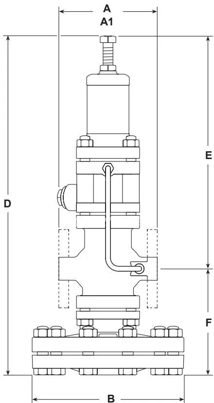
| Model Series | Nominal Size | Face-to-Face A (mm) | Width B (mm) | Height D (mm) | Center-to-Top E (mm) | Center-to-Bottom F (mm) | Weight (kg) |
|---|---|---|---|---|---|---|---|
| DP27, DP27E, DP27Y | DN15LC Screwed | 160 | 185 | 406 | 276 | 130 | 13.2 |
| DP27, DP27E, DP27Y | DN15 Screwed | 160 | 185 | 406 | 276 | 130 | 13.2 |
| DP27, DP27E, DP27Y | DN20 Screwed | 160 | 185 | 406 | 276 | 130 | 13.2 |
| DP27, DP27E, DP27Y | DN25 Screwed | 180 | 207 | 430 | 282 | 148 | 14.2 |
| DP27G, DP27GY | DN15 Screwed | 160 | 185 | 364 | 234 | 130 | 12.0 |
| DP27G, DP27GY | DN20 Screwed | 160 | 185 | 364 | 234 | 130 | 12.0 |
| DP27G, DP27GY | DN25 Screwed | 180 | 207 | 388 | 240 | 148 | 13.0 |
| DP27R | DN15LC Screwed | 160 | 185 | 296 | 166 | 130 | 12.2 |
| DP27R | DN15 Screwed | 160 | 185 | 296 | 166 | 130 | 12.2 |
| DP27R | DN20 Screwed | 160 | 185 | 296 | 166 | 130 | 12.2 |
| DP27R | DN25 Screwed | 180 | 207 | 320 | 172 | 148 | 13.2 |
Spare Parts Interchangeability for Screwed Connections
Component spares for screwed DP27 series valves share interchangeability designations across sizes 1/2”LC (DN15LC), 1/2” (DN15), 3/4” (DN20), and 1” (DN25). Letters identify parts shared between sizes within the product line.
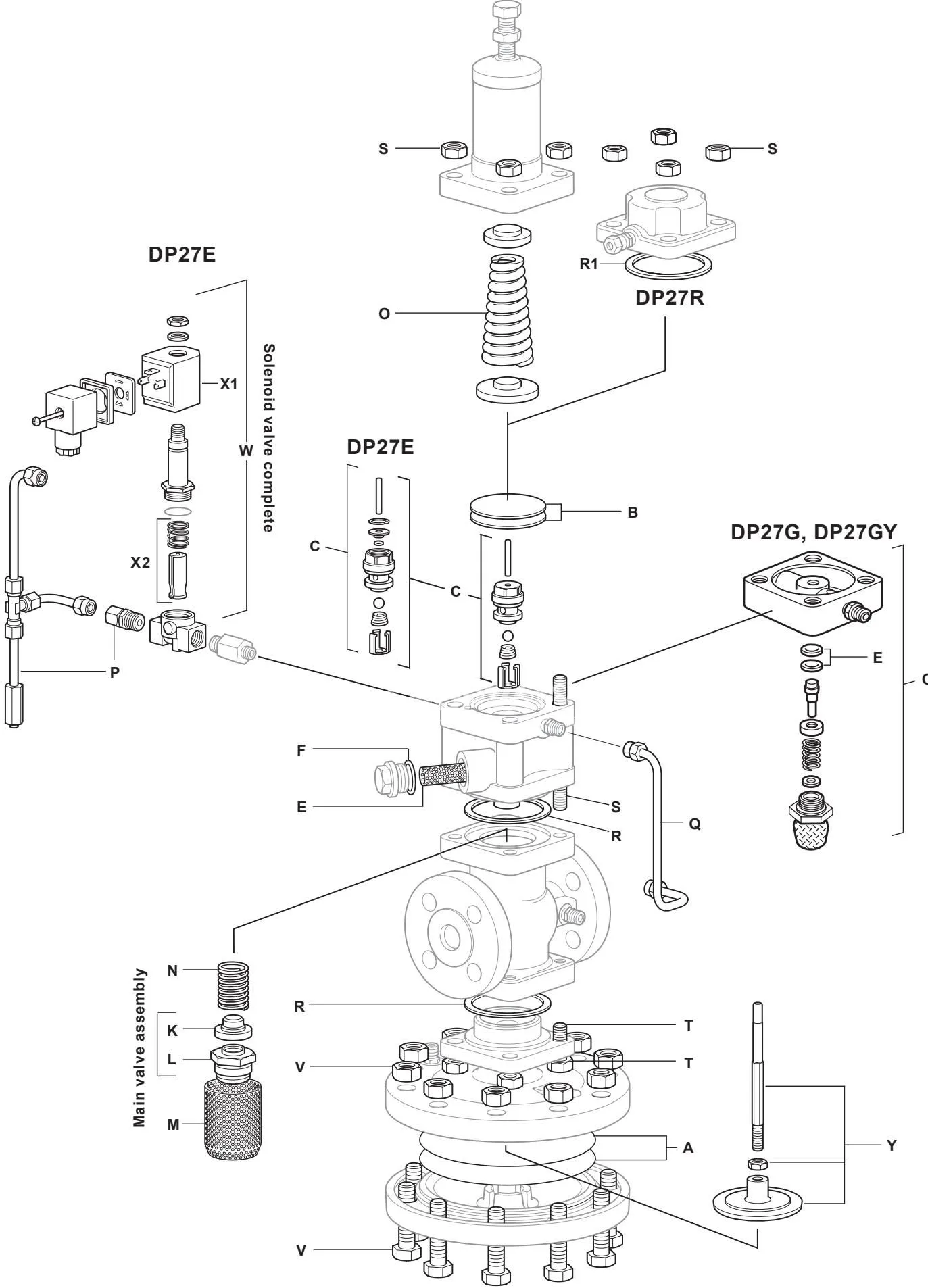
| Spare Part Item | Screwed 1/2”LC | Screwed 1/2” | Screwed 3/4” | Screwed 1” |
|---|---|---|---|---|
| Maintenance Kit | a | a | a | b |
| Main Diaphragm (2 off) | a | a | a | b |
| Pilot Diaphragms (2 off) | a | a | a | a |
| Pilot Valve Chamber Assembly | a | a | a | a |
| Pilot Filter Element | a | a | a | a |
| Pilot Filter Cap Gaskets | a | a | a | a |
| PTFE Seals | a | a | a | a |
| Main Valve Assembly | a | b | c | d |
| Internal Strainer Screen | a | a | a | b |
| Main Valve Return Spring | a | a | a | a |
| Pressure Adjustment Spring | a | a | a | a |
| Control Pipe Assembly | a | a | a | b |
| Balance Pipe Assembly | a | a | a | b |
| Body Gasket | a | a | a | a |
| Spring Housing Studs and Nuts | a | a | a | a |
| Main Body Studs and Nuts | a | a | a | a |
| Diaphragm Securing Bolts and Nuts | a (set of 10) | a (set of 10) | a (set of 10) | a (set of 10) |
| Pushrod and Main Diaphragm Plate | a | a | a | b |
Note: DP27G and DP27GY soft-seal assemblies are not interchangeable with steam-rated metal seats. When ordering spares, specify part name, valve model, and connection size (e.g., 1 - Main valve assembly for a 1” Spirax Sarco Type DP27 pressure reducing valve).
Installation and Maintenance Tightening Torques
Screwed DP27 valves must be installed horizontally with the main diaphragm chamber positioned below the pipe axis. Upstream protection by a separator with trap set and a 100-mesh strainer is required to prevent particle ingress. Specific component torques apply during maintenance:
- Spring housing securing nuts (M10 studs): 40 to 50 N m.
- Main valve seat assembly:
- DN15LC and DN15: 30 mm A/F external socket, tighten to 110 - 120 N m.
- DN20: 36 mm A/F external socket, tighten to 140 - 150 N m.
- DN25: 19 mm A/F internal socket, tighten to 230 - 250 N m.
- Pilot valve assembly (19 mm A/F hex): tighten to 45 - 50 N m using Superlube grease on threads.
- Pilot filter cap: tighten to 90 - 100 N m.
- Main diaphragm chamber bolts (M12, set of 10): tighten evenly to 80 - 100 N m (75 N m minimum).
- Pushrod lift calibration: ensure valve lift measures 2.5 mm for DN15LC, DN15, and DN20, and 3.0 mm for DN25.