
Description
Product Overview
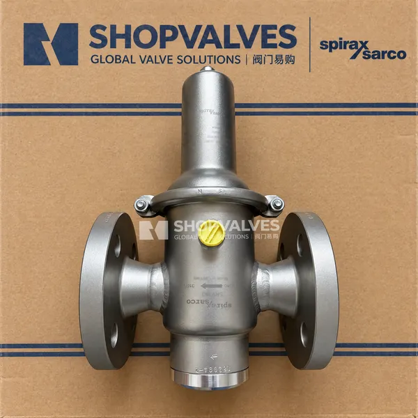
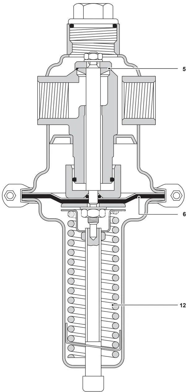
Spirax Sarco SRV463 is a flanged direct acting pressure reducing valve constructed with all wetted parts in austenitic and duplex stainless steels for steam, liquid, and gas applications. Engineered for utility and sanitary distribution systems, the valve maintains stable downstream pressure without requiring external power supplies or pilot mechanisms. The assembly modulates automatically by balancing the downward force of an adjustable control spring against downstream pressure communicated to the upper side of a two-layer diaphragm through an external sensing line connection.
Key Features
- All wetted metal components fabricated from AISI 316L (1.4404), 1.4408, 1.4462, and AISI 316Ti (1.4571) stainless steels.
- Soft seal construction utilizing Fluoraz (FEPM) seat seals and a two-layer diaphragm with a protective PTFE layer facing the process fluid, with optional FPM seat seals and diaphragms available for hydrocarbon service.
- Available Food+ execution certified according to EC 1935/2004, EC 2023/2006, EU 10/2011, and FDA 21 CFR regulations for food and beverage contact.
- Seven downstream control pressure spring ranges spanning from 0.02 bar g up to 12.00 bar g.
- Permissible reduction ratios reaching up to 80:1 on DN15 to DN25 sizes and 50:1 on DN32 to DN50 sizes.
- Tight shut-off capability with seat leakage certified not to exceed 0.05% of maximum Kv.
- Flanged connection standards conforming to EN 1759-1 Class 150, Class 300, and EN 1092-1 PN40 (as well as ASME Class 150 and EN 1092-1 PN16).
Technical Specifications
| Parameter | Flanged Class 150 / PN16 | Flanged PN40 / Class 300 |
|---|---|---|
| Nominal Sizes | DN15, DN20, DN25, DN32, DN40, DN50 | DN15, DN20, DN25, DN32, DN40, DN50 |
| Body Design Rating | PN16 / Class 150 | PN40 / Class 300 |
| Maximum Allowable Pressure | 16 bar g @ 50 °C (Class 150) / 15.2 bar g @ 50 °C (PN16) | 40 bar g @ 50 °C (Class 300/PN40) / 38 bar g @ 38 °C |
| Maximum Allowable Temperature | 200 °C @ 12.7 bar g (or 300 °C @ 9 bar g) | 200 °C @ 31.8 bar g (or 300 °C @ 23.2 bar g) |
| Minimum Allowable Temperature | -10 °C | -10 °C |
| Max. Operating Temperature (Saturated Steam) | 190 °C @ 11.5 bar g (or 190 °C @ 10.9 bar g) | 190 °C @ 11.5 bar g (or 190 °C @ 10.9 bar g) |
| Max. Operating Temperature (Liquids & Gases) | 50 °C @ 16 bar g (or 130 °C @ 12 bar g) | 50 °C @ 40 bar g (or 130 °C @ 30 bar g) |
| Max. Operating Pressure (Saturated Steam) | 11.5 bar g @ 190 °C | 11.5 bar g @ 190 °C |
| Max. Operating Pressure (Liquids & Gases) | 16 bar g @ 50 °C | 40 bar g @ 50 °C |
| Minimum Operating Temperature | -10 °C | -10 °C |
| Cold Hydraulic Test Pressure | 24 bar g | 60 bar g |
| Sensing Pipe Port | 1/4” G pipe thread | 1/4” G pipe thread |
Downstream Control Ranges and Permissible Pressure Reduction
| Setting Range (bar g) | Reduction Ratio (DN15–DN25) | Reduction Ratio (DN32–DN50) |
|---|---|---|
| 0.02 - 0.12 | 80:1 | 50:1 |
| 0.10 - 0.50 | 40:1 | 25:1 |
| 0.30 - 1.10 | 30:1 | 18:1 |
| 0.80 - 2.50 | 20:1 | 12:1 |
| 2.00 - 5.00 | 20:1 | 12:1 |
| 4.00 - 8.00 | 20:1 | 12:1 |
| 6.00 - 12.00 | 20:1 | 12:1 |
Flow Coefficients
| Valve Size | DN15 | DN20 | DN25 | DN32 | DN40 | DN50 |
|---|---|---|---|---|---|---|
| Kv at 20% offset | 4.0 | 5.6 | 6.4 | 17.6 | 17.6 | 17.6 |
| Maximum Kv | 5.0 | 7.0 | 8.0 | 22.0 | 22.0 | 22.0 |
| Seat Leakage Rate | <= 0.05% of maximum Kv | <= 0.05% of maximum Kv | <= 0.05% of maximum Kv | <= 0.05% of maximum Kv | <= 0.05% of maximum Kv | <= 0.05% of maximum Kv |
Dimensions and Weights (Flanged)
| Size | Face-to-Face A1 (mm) | Center-to-Bottom B (mm) |
|---|---|---|
| DN15 | 130 | 76 |
| DN20 | 150 | 76 |
| DN25 | 160 | 76 |
| DN32 | 180 | 90 |
| DN40 | 200 | 90 |
| DN50 | 230 | 90 |
| Set Pressure Range (bar g) | Height C (mm) | Diaphragm Diameter ∅D (mm) |
|---|---|---|
| 0.02 - 0.12 | 300 | 360 |
| 0.1 - 0.5 | 300 | 264 |
| 0.3 - 1.1 | 300 | 200 |
| 0.8 - 5.0 | 235 | 138 |
| 4.0 - 12.0 | 235 | 138 |
| Size Group | Weight: 0.02-0.12 bar (kg) | Weight: 0.1-0.5 bar (kg) | Weight: 0.3-1.1 bar (kg) | Weight: 0.8-12 bar (kg) |
|---|---|---|---|---|
| DN15 - DN25 (Flanged) | 15.3 | 8.9 | 7.9 | 4.9 |
| DN32 - DN50 (Flanged) | 18.4 | 12.0 | 11.0 | 8.0 |
Materials of Construction
| Item | Component | Material | Werkstoff No. | AISI Equivalent |
|---|---|---|---|---|
| 1 | Body | Stainless steel | 1.4404 | 316L |
| 2 | Spring housing | Stainless steel | 1.4404 | 316L |
| 3 | Cap | Stainless steel | 1.4571 | 316Ti |
| 4 | Valve seat | Stainless steel | 1.4404 | 316L |
| 5 | Valve | Stainless steel | 1.4404 | 316L |
| 6 | Diaphragm | EPDM/PTFE | - | - |
| 7, 8, 9 | ‘O’ rings | FEPM (Fluoraz) | - | - |
| 10 | Piston | Stainless steel | 1.4571 | 316Ti |
| 11 | Top spring plate | Stainless steel | 1.4571 | 316Ti |
| 12 | Spring | Stainless steel | 1.4310 | 301 |
| 13 | Adjustment screw | Stainless steel | 1.4404 | 316L |
| 14 | V-band clamp | Stainless steel | AISI 300 series | - |
| 15 | Flange | Stainless steel | 1.4404 | 316L |
| 16 | Soft seal | FEPM (Fluoraz) | - | - |
| 17 | Spring clip | Stainless steel | 1.4301 | 304 |
Applications
- Clean steam supply systems
- Gas and liquid distribution to centrifuges
- Freeze dryers and freeze drying equipment
- Autoclaves and hospital or laboratory sterilisers
- Process reactors and fluid storage tanks
- Clean steam humidifiers
- Culinary steam supplies and food contact installations conforming to EC 1935/2004
Installation and Sizing Guidelines
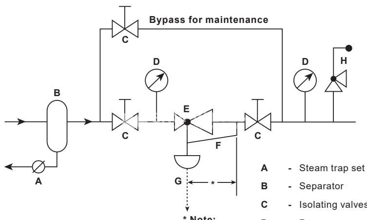
Spirax Sarco SRV463 must be fitted in a horizontal pipeline. On steam applications, the adjustment head and spring housing must be positioned below the pipeline to allow condensate to fill the diaphragm chamber. Upstream steam lines must be drained using a drain pocket or separator and a steam trap set.
Key installation requirements include:
- Pipe isolation valves must provide a clear run of at least 10 pipe diameters upstream and downstream of the valve without transferring line stresses to the valve flanges.
- Line expansions or contractions must utilize eccentric reducers to prevent water collection.
- A pipeline strainer should be installed upstream, preferably mounted on its side to avoid collecting condensate in the screen pocket.
- Connect a 1/4” pressure sensing line to a straight section of pipe at least 15 pipe diameters downstream of the valve and at least 10 diameters downstream of any pipe fitting.
- On steam service, pitch the sensing line upwards toward the steam line so that condensate drains into the diaphragm housing. If downstream pressure is below 0.1 bar g, fit a damping pot into the sensing line.
- For Food+ installations, an appropriate CIP (cleaning-in-place) cycle must be completed prior to initial operation.
Maintenance and Spare Parts
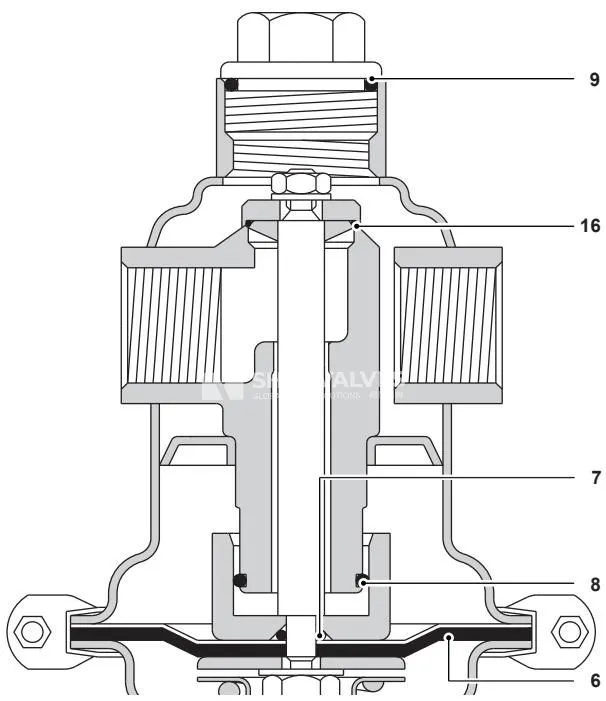
Before servicing, isolate line pressure, allow the valve to cool, and turn the adjustment screw fully counterclockwise to relieve all control spring compression.
Available Spares
- Diaphragm and ‘O’ ring kit: includes diaphragm (6), internal O-rings (7, 8, 9), and valve soft seal (16).
When ordering replacement spare kits, specify the nominal size, model designation SRV463 or SRV463S, the applicable pressure range, and whether the standard or Food+ variant is installed. For Food+ applications, a CIP cycle must be executed following reassembly.