
Description
Product Overview
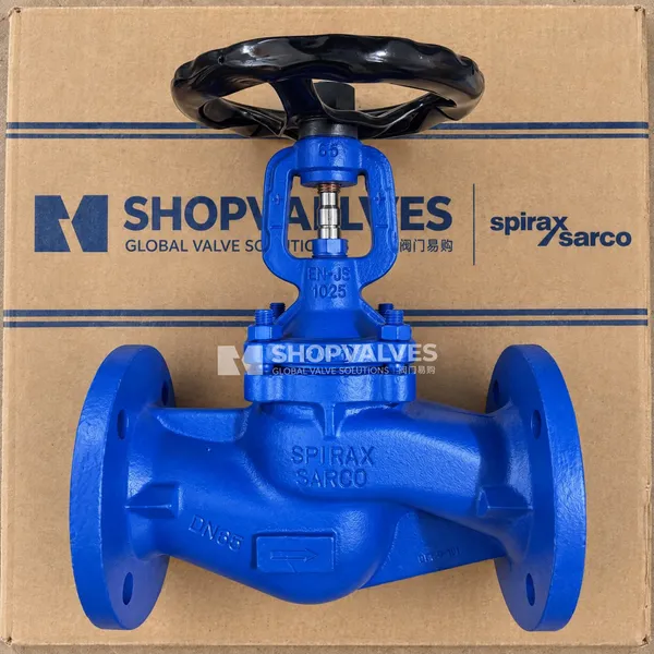
Spirax Sarco BSA2 is an SG iron bellows sealed in-line stop valve engineered for isolation and throttling across industrial utility networks. Installed on steam, condensate, liquid, gas, and compressed air systems, it eliminates fugitive stem emissions to conserve thermal energy and maintain pipeline integrity.
Manufactured from EN-GJS-400-18-LT (5.3103) SG iron for both body and bonnet, the BSA2 model envelope encompasses standard flat disc isolation valves, BSA2T throttling plug configurations with stroke limiting hardware, and BSA2-BD (BSA2B/D) balancing disc valves for applications with elevated differential pressures. Pipeline connections conform to flanged EN 1092 / ISO 7005 PN16 and PN25 ratings with face-to-face dimensions to EN 558.
Key Features
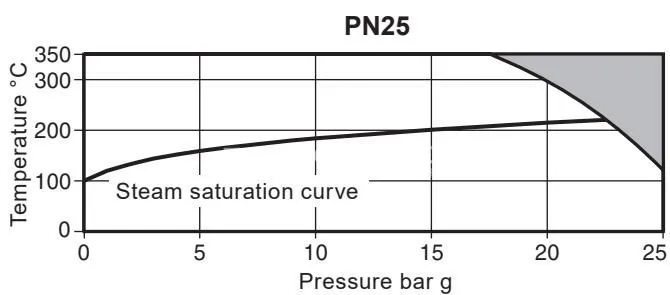
- Ductile iron construction: body and bonnet cast in SG iron EN-GJS-400-18-LT (5.3103) rated up to 25 bar g design pressure and 350 °C maximum allowable temperature.
- Hermetic stem sealing: stainless steel bellows unit (WS 1.4571) isolates line fluid from the atmosphere, supported by graphite secondary stem packing.
- Tight shut-off performance: disc-to-seat shut-off complies with EN 12266-1 Rate A leakage standards.
- Throttling option compatibility: BSA2T version integrates a contoured throttling plug, stem locking screw, and handwheel nut tapped for an external stroke limiting bolt.
- Balancing disc configuration: BSA2-BD provides a two-stage pre-lifting pilot plug assembly for high differential pressure closure above size DN125.
- Soft seating insert option: optional R-PTFE (25% carbon filled) soft disc insert available from DN15 to DN100 for bubble-tight shut-off up to 230 °C.
- Certification: EN 10204 3.1 material and inspection certification available when specified at the time of order placement.
Technical Specifications
| Specification Parameter | BSA2 / BSA2T PN16 | BSA2 / BSA2T PN25 |
|---|---|---|
| Body & Bonnet Material | SG iron EN-GJS-400-18-LT (5.3103) | SG iron EN-GJS-400-18-LT (5.3103) |
| Seat Material | Stainless steel AISI 420 | Stainless steel AISI 420 |
| Disc Material | Stainless steel DIN 17440 X30 Cr13 | Stainless steel DIN 17440 X30 Cr13 |
| Optional Soft Seat Insert | R-PTFE (25% carbon filled, DN15-DN100) | R-PTFE (25% carbon filled, DN15-DN100) |
| Bellows Material | Stainless steel WS 1.4571 | Stainless steel WS 1.4571 |
| Stem Material | Stainless steel AISI 420 | Stainless steel AISI 420 |
| Body/Bonnet Gasket | Graphite laminated with stainless steel insert | Graphite laminated with stainless steel insert |
| Nominal Size Range | DN15 to DN200 | DN15 to DN250 |
| Flange Standard | EN 1092 / ISO 7005 PN16 | EN 1092 / ISO 7005 PN25 |
| Face-to-Face Standard | EN 558 | EN 558 |
| PMA (Maximum Allowable Pressure) | 16 bar g | 25 bar g |
| TMA (Maximum Allowable Temperature) | 350 °C | 350 °C |
| PMO (Max Operating Pressure, Sat. Steam) | 14.7 bar g | 22.3 bar g |
| TMO Metal Seat | 350 °C | 350 °C |
| TMO Soft Seat (R-PTFE) | 230 °C | 230 °C |
| Minimum Operating Temperature | -10 °C | -10 °C |
| Cold Hydraulic Test Pressure | 24 bar g | 38 bar g |
| Leakage Standard | EN 12266-1 Rate A / ISO 5208 Rate A | EN 12266-1 Rate A / ISO 5208 Rate A |
Applications
- Saturated steam distribution manifolds and terminal branch line isolation
- Condensate return systems and pumped condensate collection mains
- Industrial hot water and district heating circuits
- Compressed air supply networks and gas distribution lines
- Utility installations governed by European Pressure Equipment Directive 2014/68/EU Group 2 fluids
Dimensions and Physical Properties
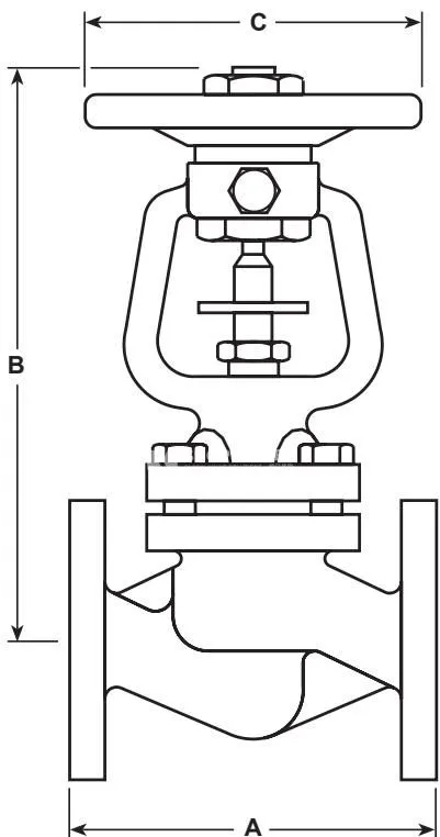
| Size | Face-to-Face A (mm) | Height B (mm) | Handwheel C (mm) | Weight (kg) |
|---|---|---|---|---|
| DN15 | 130 | 205 | 125 | 4 |
| DN20 | 150 | 205 | 125 | 4 |
| DN25 | 160 | 217 | 125 | 5 |
| DN32 | 180 | 217 | 125 | 7 |
| DN40 | 200 | 243 | 200 | 10 |
| DN50 | 230 | 243 | 200 | 12 |
| DN65 | 290 | 263 | 200 | 16 |
| DN80 | 310 | 287 | 200 | 21 |
| DN100 | 350 | 383 | 315 | 36 |
| DN125 | 400 | 416 | 315 | 52 |
| DN150 | 480 | 450 | 400 | 75 |
| DN200 | 600 | 622 | 500 | 145 |
| DN250 (PN25 only) | 730 | 763 | 500 | 180 |
Full-open flow coefficients (Kv values) for standard BSA2 valves:
- DN15: 4 m³/h
- DN20: 7 m³/h
- DN25: 12 m³/h
- DN32: 19 m³/h
- DN40: 30 m³/h
- DN50: 47 m³/h
- DN65: 77 m³/h
- DN80: 120 m³/h
- DN100: 193 m³/h
- DN125: 288 m³/h
- DN150: 410 m³/h
- DN200: 725 m³/h
- DN250: 1145 m³/h
Throttling Control and Flow Characteristics (BSA2T)
BSA2T configurations are fitted with a profiled throttling plug to provide proportional flow control across handwheel rotations. Once set, the locking screw is tightened down to suppress vibration.
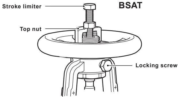
The handwheel nut features a threaded provision for fitting a stroke limiter bolt:
- DN15 - DN80: M8 x 50 mm hexagon bolt
- DN100 - DN150: M12 x 75 mm hexagon bolt
- DN200 - DN250: M12 x 100 mm hexagon bolt
Maximum permissible differential pressure in throttling duty:
- DN15 - DN80: 2.0 bar (29.00 psi)
- DN100 - DN125: 1.5 bar (21.75 psi)
- DN150: 1.0 bar (14.50 psi)
- DN200 - DN250: 0.8 bar (11.60 psi)
Kv values according to handwheel turns (water at 20 °C to EN 60534-2-3):
| Handwheel Rotations | DN15 | DN20 | DN25 | DN32 | DN40 | DN50 | DN65 | DN80 | DN100 | DN125 | DN150 | DN200 | DN250 |
|---|---|---|---|---|---|---|---|---|---|---|---|---|---|
| 0 | 0 | 0 | 0 | 0 | 0 | 0 | 0 | 0 | 0 | 0 | 0 | 0 | 0 |
| 0.5 | 1.2 | 1.2 | 1.4 | 2.2 | 4.4 | 4.1 | 5.6 | 10.4 | 12.0 | 21 | 28 | 66 | 110 |
| 1.0 | 1.7 | 1.7 | 2.0 | 3.7 | 5.0 | 5.0 | 7.0 | 11.5 | 14.3 | 23 | 30 | 81 | 140 |
| 1.5 | 2.7 | 2.9 | 2.9 | 5.0 | 5.5 | 6.0 | 9.2 | 13.6 | 24.5 | 26 | 33 | 97 | 150 |
| 2.0 | 3.6 | 4.0 | 4.6 | 7.9 | 7.6 | 7.2 | 11.6 | 16.3 | 34.1 | 42 | 46 | 111 | 165 |
| 2.5 | 4.4 | 5.3 | 6.4 | 10.6 | 11.0 | 9.7 | 12.4 | 18.5 | 59.6 | 67 | 65 | 149 | 190 |
| 3.0 | 5.4 | 6.6 | 8.5 | 13.8 | 14.7 | 14.1 | 13.0 | 21.1 | 86.2 | 94 | 90 | 199 | 225 |
| 4.0 | - | - | 10.6 | 17.0 | 22.6 | 24.4 | 25.2 | 24.5 | 123.0 | 140 | 152 | 302 | 330 |
| 5.0 | - | - | 11.9 | 19.6 | 27.2 | 37.0 | 43.6 | 39.1 | 164.1 | 185 | 216 | 403 | 460 |
| 6.0 | - | - | - | - | 28.9 | 46.2 | 60.2 | 61.0 | 179.0 | 220 | 264 | 455 | 600 |
| 7.0 | - | - | - | - | - | - | 65.9 | 78.0 | - | 241 | 305 | 495 | 678 |
| 8.0 | - | - | - | - | - | - | 71.2 | 90.0 | - | 259 | 337 | 507 | 738 |
| 9.5 | - | - | - | - | - | - | - | 99.0 | - | - | 369 | - | 793 |
| 10.7 | - | - | - | - | - | - | - | - | - | - | - | - | 827 |
High Differential Pressure Balancing Disc (BSA2-BD)
When line differential pressures exceed specified limits on larger valves, manual shut-off against flow becomes impossible without pilot assistance. BSA2-BD valves incorporate a two-stage internal mechanism comprising a pre-lifting pilot plug (A) and a main disc (B).
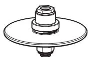
Balancing discs are required when system differential pressure exceeds:
- DN125: > 25 bar ΔP
- DN150: > 17 bar ΔP
- DN200: > 10 bar ΔP
- DN250: > 6 bar ΔP (BSA2 only)
Installation requirement: On BSA2-BD valves, the flow direction must be reversed compared to standard stop valves. Upstream medium must enter on the bellows side into the upper valve chamber so that fluid pressure acts on top of the balancing disc to assist positive seating. If upgrading an existing BSA2 in-line, the valve body must be rotated 180° in the pipeline and clearly re-marked with a new flow direction arrow.
Maintenance, Bolting Torques and Spare Parts
All internal components of the BSA2 can be replaced in-line without removing the body from the pipeline. System pressure must be completely vented to atmospheric pressure and the assembly allowed to cool before loosening fasteners.
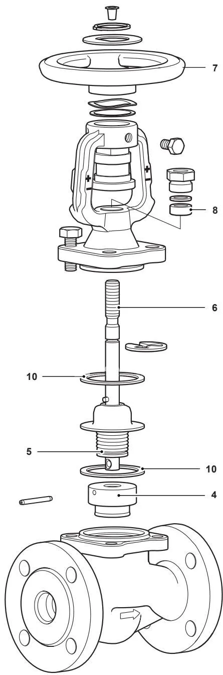
Recommended bonnet stud tightening torques for BSA2 and BSA2T (PN16 and PN25):
- DN15 - DN32 (17 mm A/F): 35 - 40 N m (26 - 29 lbf ft)
- DN40 - DN65 (19 mm A/F): 55 - 60 N m (40 - 44 lbf ft)
- DN80 - DN150 (24 mm A/F): 130 - 140 N m (95 - 103 lbf ft)
- DN200 (30 mm A/F): 260 - 280 N m (191 - 206 lbf ft)
- DN250 (36 mm A/F): 480 - 520 N m (352 - 382 lbf ft)
Handwheel retention torques:
- DN40 - DN80: handwheel nut has a left-handed thread; tighten anticlockwise to 40 N m (29 lbf ft).
- DN100 - DN250: apply Loctite 638 to handwheel boss threads and torque to 50 N m (36 lbf ft); tighten the left-handed handwheel nut anticlockwise to 40 N m (29 lbf ft).
Available spare part kits:
- Body/bonnet gasket and stem packing kit: includes body gasket (10b), bellows collar gasket (10a), and stem graphite packing ring (8).
- Stem and bellows assembly kit: includes stem and bellows assembly (6, 5), gaskets (10a, 10b), and packing ring (8).
- Disc kit: includes disc (4), replacement stem pin or collet/retaining hardware, gaskets (10a, 10b), and packing ring (8).
- Replacement handwheel (7).