
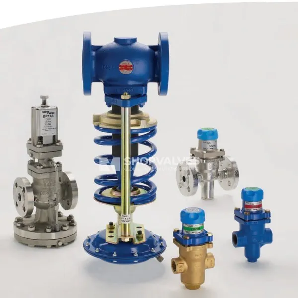
Description
Product Overview
Spirax Sarco DRV4 is a cast steel, direct acting bellows sealed pressure reducing valve designed for steam, water, compressed air, and gas distribution systems. Operating without external electric or pneumatic power supplies, it stabilizes downstream pressure by balancing downstream pressure acting on an actuator diaphragm against an adjustable mechanical control spring.
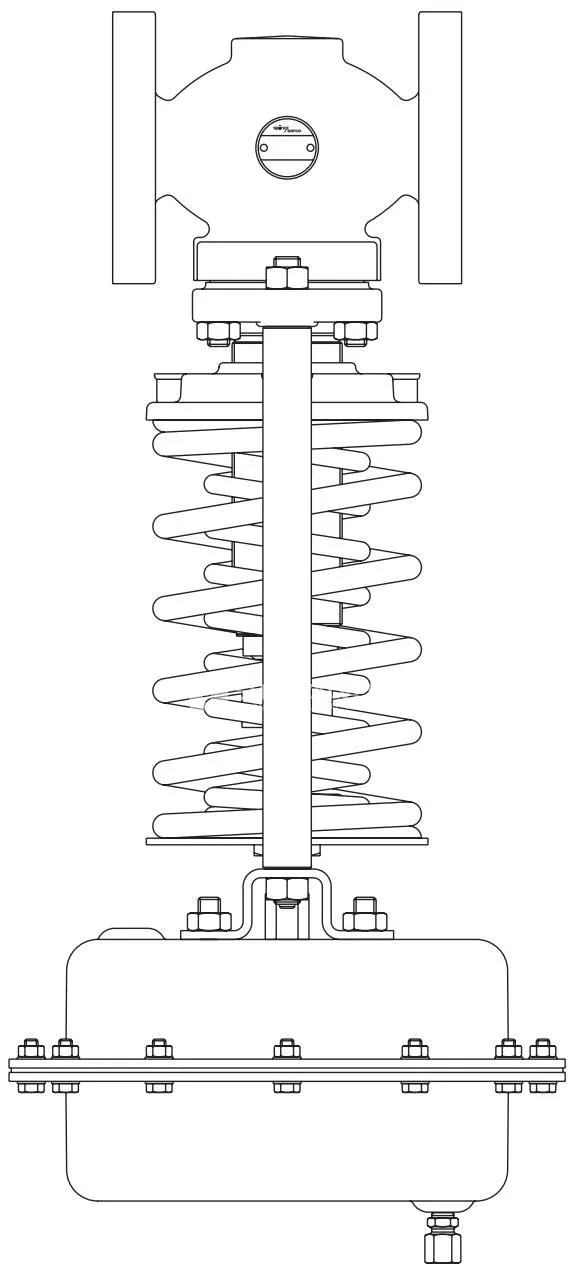
The standard configuration features an EPDM fabric-reinforced diaphragm and stainless steel internal bellows seals. Sizes DN15 and DN20 incorporate a plug-balanced design, while sizes DN25 through DN100 feature a fully balanced construction with an internal balancing bellows. For tight shut-off on air and gas applications, the DRV4G soft-seated variant incorporates a Nitrile rubber seat rated up to 90 °C. When handling oil systems, the valve is supplied with a Nitrile rubber diaphragm designated by suffix ‘N’. When installed on steam duty, a WS4 series water seal pot must be placed in the downstream impulse line to protect the actuator diaphragm.
Key Features
- Direct acting, self-powered design requires no auxiliary electrical or compressed air power supplies.
- Stainless steel AISI 316L stem sealing bellows prevents stem leakage and eliminates gland packing maintenance.
- Balanced trim construction incorporates plug balancing on DN15–DN20 and balancing bellows on DN25–DN100 to isolate downstream control from upstream pressure fluctuations.
- Six distinct actuator and spring combinations provide controlled downstream set pressures from 0.1 bar g to 20.0 bar g.
- Flanged cast steel GP 240 GH body rated PN40 withstands operating temperatures up to 300 °C at 25.8 bar g.
- DRV4G soft seated version with Nitrile trim provides tight shut-off up to 90 °C for gas and air networks with up to 10:1 turndown.
- Certification according to EN 10204 3.1 is available upon request.
Technical Specifications
Pressure and Temperature Limits
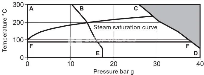
| Parameter | DRV4 (Standard Seat) | DRV4G (Soft Seat) |
|---|---|---|
| Body Design Rating | PN40 | PN40 |
| Maximum Design Pressure (PMA) | 40 bar g @ 50 °C | 40 bar g @ 50 °C |
| Maximum Design Temperature (TMA) | 300 °C @ 25.8 bar g | 90 °C @ 37.3 bar g |
| Minimum Design Temperature | 0 °C | 0 °C |
| Maximum Operating Temperature (TMO) | 300 °C @ 25.8 bar g | 90 °C @ 37.3 bar g |
| Minimum Operating Temperature | 0 °C | 0 °C |
| Maximum Saturated Steam Pressure | 32 bar g | Not applicable |
| Maximum Differential Pressure (DN15–DN50) | 25 bar | 25 bar |
| Maximum Differential Pressure (DN65–DN100) | 20 bar | 20 bar |
| Cold Hydraulic Test Pressure (No internals) | 60 bar g | 60 bar g |
| Cold Hydraulic Test Pressure (Internals fitted) | 40 bar g | 40 bar g |
| Maximum Actuator Continuous Temperature | 125 °C (EPDM) / 90 °C (Nitrile) | 125 °C (EPDM) / 90 °C (Nitrile) |
Downstream Pressure Ranges and Actuator Data
| Range | Valve Type | Actuator Type | Spring Colour | Pressure Range (bar g) | Actuator Housing PN |
|---|---|---|---|---|---|
| 1 | DRV4(G)B1(N) | 1 or 1N | Yellow | 0.1 – 0.6* | PN2.5 |
| 2 | DRV4(G)B2(N) | 2 or 2N | Yellow | 0.2 – 1.2** | PN2.5 |
| 3 | DRV4(G)B3(N) | 3 or 3N | Blue | 0.8 – 2.5 | PN6.0 |
| 4 | DRV4(G)B4(N) | 4 or 4N | Blue | 2.0 – 5.0 | PN16.0 |
| 5 | DRV4(G)B5(N) | 5 or 5N | Blue | 4.5 – 10.0 | PN25.0 |
| 6 | DRV4(G)B6(N) | 5 or 5N | Red | 8.0 – 20.0 | PN25.0 |
* For DN32–DN50: range is 0.15 – 0.6 bar g; for DN65–DN100: range is 0.30 – 0.6 bar g.
** For DN65–DN100: range is 0.40 – 1.2 bar g.
Flow Coefficients (Kvs)
| Size | DN15 | DN20 | DN25 | DN32 | DN40 | DN50 | DN65 | DN80 | DN100 |
|---|---|---|---|---|---|---|---|---|---|
| Kvs (m³/h) | 3.4 | 6.5 | 11.4 | 16.4 | 24.0 | 40.0 | 58.0 | 92.0 | 145.0 |
| Cv (UK) | 3.27 | 6.26 | 10.98 | 15.79 | 23.11 | 38.52 | 55.85 | 88.60 | 139.64 |
| Cv (US) | 3.93 | 7.51 | 13.18 | 18.96 | 27.74 | 46.24 | 67.05 | 106.35 | 167.62 |
Construction Materials
| Item | Component | Valve Size / Type | Material | Standard Specification |
|---|---|---|---|---|
| 1 | Body | All sizes | Cast steel | GP 240 GH / DIN 17245 GP 240 GH |
| 2 | Bonnet | All sizes | Cast steel | GS C25 / DIN 17425 GS C25 |
| 3 | Valve seat | All sizes | Stainless steel | BS 970 431 S29 |
| 4 | Seat gasket | DN15 | Stainless steel | — |
| DN20–DN25 | Mild steel | — | ||
| DN32–DN50 | Graphite | Reinforced exfoliated graphite | ||
| 5 | Valve head | DRV4 | Stainless steel | BS 970 431 S29 |
| DRV4G | Stainless steel / Nitrile | BS 970 431 S29 / Nitrile | ||
| 6 | Valve head screw | DN15–DN20 | Stainless steel | BS 6105 A2 |
| 7 | Valve head seal | All sizes | Arlon 1555 | — |
| 8, 9 | Guide bush | DN15–DN100 | Stainless steel | BS 970 431 S29 |
| 10 | Balancing bellows | DN25–DN100 | Stainless steel | AISI 316L |
| 11 | Balancing bellows gasket | DN25–DN100 | Graphite | Reinforced exfoliated graphite |
| 12 | Bonnet gasket | All sizes | Graphite | Reinforced exfoliated graphite |
| 13 | Bonnet nuts | All sizes | Steel | DIN 267 Pt13 Gr. 8 |
| 14 | Bonnet studs | DN15–DN40 (M10), DN50–DN65 (M12), DN80–DN100 (M16) | Steel | DIN 267 Pt13 Gr. 8.8 |
| 15 | Pillars | All sizes | Zinc plated steel | BS 970 230 M07 |
| 17 | Spring adjuster | All sizes | Zinc plated cast iron | DIN 1691 GG25 |
| 18 | Control spring | All sizes | Chrome vanadium steel | — |
| 20 | Sealing bellows assembly | All sizes | Stainless steel | AISI 316L |
| 21 | Sealing bellows gasket | DN15–DN20 | Stainless steel | ‘S’ type |
| DN25–DN100 | Graphite | Reinforced exfoliated graphite | ||
| 22 | Clamp nut | DN25–DN100 | Zinc plated steel | BS 970 230 M07 |
| 27 | Needle bearing | All sizes | Steel | — |
| 32 | Actuator housing | Types 1(N)–4(N) | Steel | DIN 1514 St W24 |
| Type 5(N) | Steel | BS EN 10025 S355 J2G3 | ||
| 35 | Diaphragm | Standard | EPDM | Fabric reinforced |
| Suffix ‘N’ | Nitrile | Fabric reinforced | ||
| 38 | Diaphragm clamp | All types | Stainless steel | ASTM A351 CF8M |
| 45 | Clamp plate | DN65–DN100 | Stainless steel | ASTM A276 316L |
| 46 | Clamp plate gasket | DN65–DN100 | Graphite | Reinforced exfoliated graphite |
Dimensions and Weights
| Size | Face-to-Face EN 1092 PN40 (mm) | Face-to-Face ASME 300 (mm) | Face-to-Face ASME 150 (mm) | Height B / Actuator 1 (mm) | Height B / Actuator 2 (mm) | Height B / Actuator 3 (mm) | Height B / Actuator 4 (mm) | Height B / Actuators 5+6 (mm) | Valve Weight (Yellow/Blue Spring) (kg) | Valve Weight (Red Spring) (kg) |
|---|---|---|---|---|---|---|---|---|---|---|
| DN15 | 130 | 130 | 124 | 537 | 511 | 426 | 426 | 411 | 11.0 | 12.0 |
| DN20 | 150 | 150 | 143 | 537 | 511 | 426 | 426 | 411 | 12.4 | 13.4 |
| DN25 | 160 | 162 | 153 | 546 | 520 | 435 | 435 | 420 | 14.6 | 15.6 |
| DN32 | 180 | 181 | 176 | 608 | 582 | 497 | 497 | 482 | 19.8 | 21.2 |
| DN40 | 200 | 203 | 198 | 608 | 582 | 497 | 497 | 482 | 21.2 | 22.6 |
| DN50 | 230 | 233 | 229 | 611 | 585 | 500 | 500 | 485 | 25.2 | 26.6 |
| DN65 | 290 | 297 | 295 | 633 | 607 | 522 | 522 | 507 | 35.5 | 37.3 |
| DN80 | 310 | 319 | 314 | 639 | 613 | 528 | 528 | 513 | 41.3 | 43.1 |
| DN100 | 350 | 366 | 350 | 744 | 718 | 633 | 633 | 618 | 58.3 | 60.9 |
Actuator weights: Type 1/1N = 12.3 kg; Type 2/2N = 6.5 kg; Type 3/3N = 3.9 kg; Type 4/4N = 2.5 kg; Type 5/5N = 2.6 kg. Total product weight is calculated by adding valve body weight and actuator weight.
Applications
- Saturated steam distribution and process equipment pressure reduction.
- Compressed air industrial networks requiring steady supply pressures.
- Inert industrial gases in plant utility distributions.
- Gas and air lines requiring tight shut-off up to 90 °C using DRV4G soft-seated construction.
- Industrial oil systems with Group 2 fluids using Nitrile rubber diaphragm trim (suffix ‘N’).
- Intermittent liquid service (continuous pump recirculation service is excluded to prevent cavitation damage).
Installation Guidelines
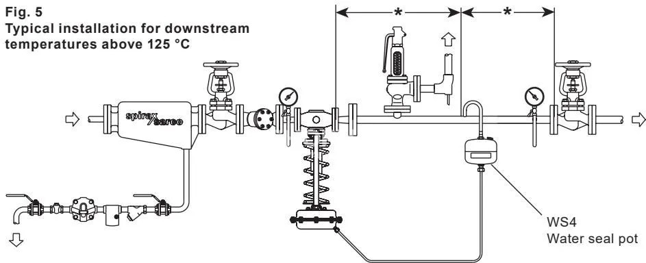
Spirax Sarco DRV4 must be installed in a horizontal pipeline adhering to the flow arrow cast on the valve body. For media operating temperatures below 125 °C, the valve may be oriented with the actuator pointing vertically downwards or upwards. For steam service or temperatures exceeding 125 °C, the valve must be positioned vertically downwards with the actuator below the pipework, protected by an intermediate water seal pot.
Key piping layout requirements:
- Connect the downstream impulse line using 8 mm copper or stainless steel pipe of at least 1 metre length.
- Locate the sensing point at least 1 metre or 15 pipe diameters away from the valve outlet or adjacent fittings to ensure stable pressure transmission.
- Install an upstream pipeline strainer installed horizontally on its side to trap pipeline debris without creating water collection pockets.
- Fit an upstream steam separator and steam trap station on steam service lines to deliver dry steam.
- Position pressure gauges upstream and downstream to verify commissioning and set pressure adjustment.
- Install a downstream safety valve sized to pass full DRV4 capacity in case of unexpected pressure surges.
- Charge the water seal pot fully with soft water before placing steam lines into service.
Valve Lift and Pressure Adjustment
Downstream pressure is adjusted by rotating spring adjuster (17) while monitoring the downstream pressure gauge. An open-ended spanner (17 mm A/F for DN15–DN50, 24 mm A/F for DN65–DN100) is used: compressing the spring raises set pressure, while releasing spring tension lowers it. When setting maximum valve lift after servicing, setting nut (28) must be adjusted according to the turns and flats listed below while keeping lock-nut (25) loose.
| Valve Size | Maximum Lift (mm) | Setting Nut Adjustment (Turns and Flats) |
|---|---|---|
| DN15 | 4.00 | 2 turns, 4 flats |
| DN20 | 4.75 | 3 turns, 1 flat |
| DN25 | 6.25 | 4 turns, 1 flat |
| DN32 | 7.75 | 5 turns, 1 flat |
| DN40 | 9.00 | 6 turns |
| DN50 | 11.00 | 7 turns, 2 flats |
| DN65 | 12.25 | 8 turns, 1 flat |
| DN80 | 15.75 | 10 turns, 3 flats |
| DN100 | 19.50 | 13 turns |
Recommended Tightening Torques
| Component | Size / Type | Torque (N·m) |
|---|---|---|
| Valve seat (3) | DN15 | 50 – 55 |
| DN20 | 105 – 110 | |
| DN25 | 160 – 170 | |
| DN32 | 100 – 110 | |
| DN40 | 175 – 185 | |
| DN50 | 165 – 175 | |
| Balancing bellows assembly (10) | DN25 | 90 – 100 |
| DN32–DN40 | 170 – 180 | |
| DN50 | 220 – 230 | |
| Adaptor (23) | DN25–DN50 | 55 – 60 |
| Balancing to sealing bellows connection | DN25–DN100 | 2 – 3 |
| Clamp nut (22) | DN25–DN50 | 40 – 45 |
| DN65–DN100 | 60 – 65 | |
| Bonnet nuts (13) | DN15 | 15 – 20 |
| DN20 | 20 – 25 | |
| DN25–DN50 | 25 – 30 | |
| DN65 | 40 – 45 | |
| DN80 | 60 – 65 | |
| DN100 | 50 – 55 | |
| Guide bush (8) | DN15–DN20 only | 50 – 60 |
| Pillar nuts (16) | All sizes | 25 – 35 |
| Sealing bellows assembly (20) | DN15–DN20 only | 175 – 185 |
| Setting nut / lock nut (28/25) | All sizes | 10 – 15 |
| Actuator housing bolts/nuts (33/34) | Types 1, 1N, 2, 2N | 4.5 – 5.5 |
| Actuator housing bolts/nuts (33/34) | Types 3, 3N, 4, 4N, 5, 5N | 10.5 – 11.5 |
| Diaphragm clamp bolt (36) | All actuators | 23 – 27 |
| Actuator mounting nuts (41) | All actuators | 15 – 18 |
Spare Parts
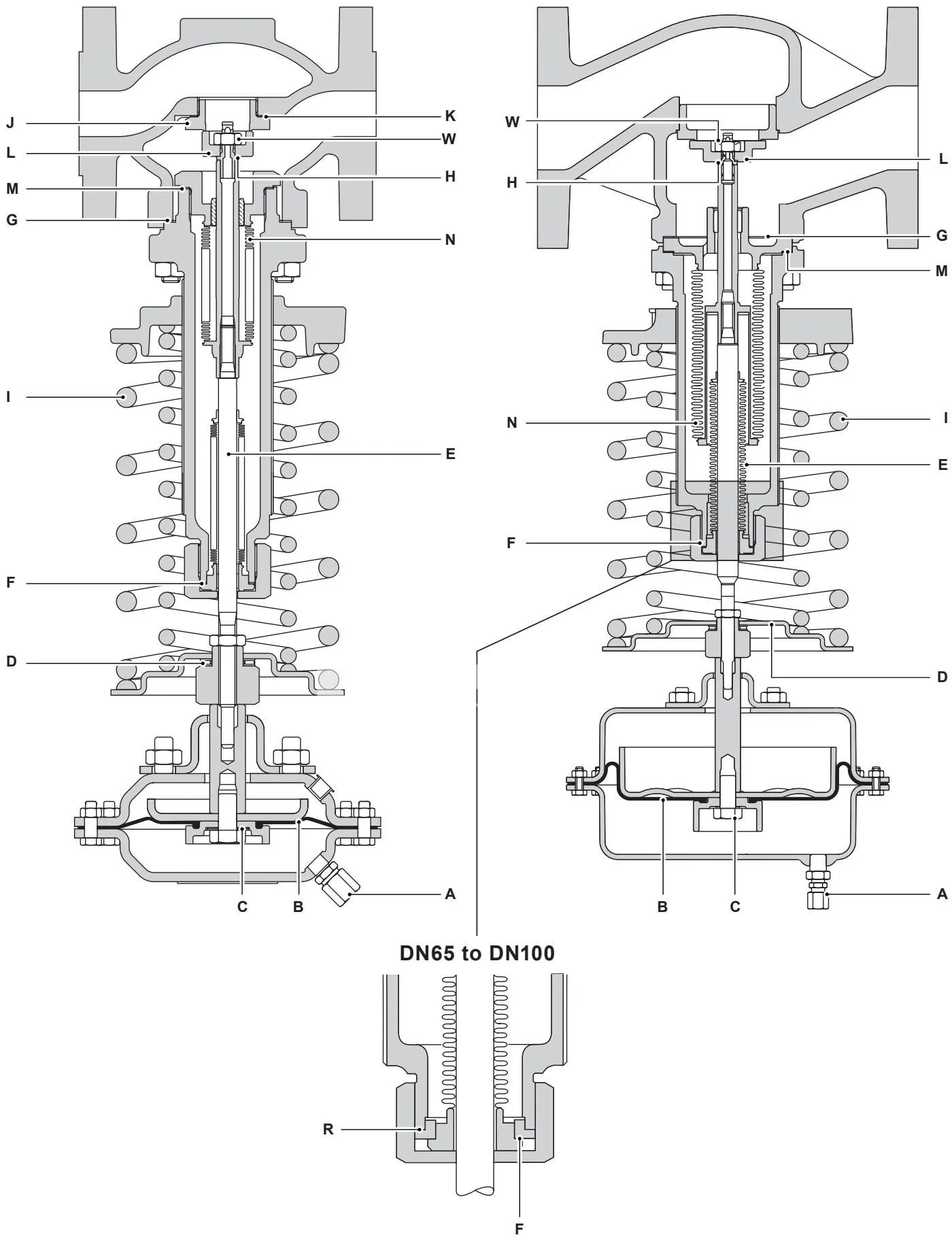
Available spare kits for maintenance:
- Diaphragm set (diaphragm and fibre sealing washer).
- Needle bearing kit (bearing assembly).
- Sealing bellows kit (sealing bellows, bellows gasket, bonnet gasket, plus adaptor/clamp plate gaskets as applicable).
- Control spring set (individual color-coded springs).
- Seat and head set (seat, seat gasket, valve head, head seal, bonnet gasket, self-locking nut).
- Balancing bellows kit for DN25–DN100 (balancing bellows assembly, gaskets, self-locking nut, head seal).
- Gasket set (complete body, bellows, and bonnet graphite/steel replacement seals).