
Description
Product Overview
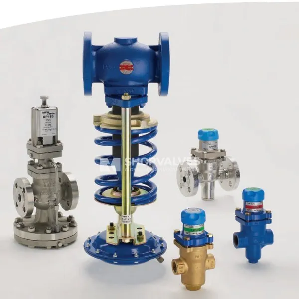
Spirax Sarco DRV7 direct acting pressure reducing valve regulates fluid pressure without requiring external power supplies or pilot controls. Installed in industrial distribution lines, this unit reduces fluctuating upstream pressures to maintain constant downstream set points across steam, compressed air, gas, and intermittent liquid installations. The assembly utilizes an SG iron (ductile iron) body rated PN25, a single-seat configuration, and a stainless steel bellows seal on the stem to eliminate routine gland packing maintenance.
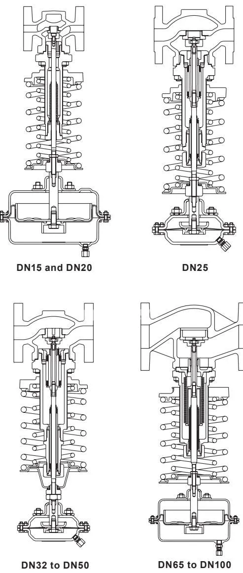
Actuation relies on downstream pressure piped directly to an elastomer diaphragm actuator opposing a calibrated control spring. Balanced internal construction stabilizes the valve against inlet pressure variations: DN15 and DN20 sizes employ a plug-balanced trim, whereas sizes DN25 through DN100 incorporate an AISI 316L stainless steel balancing bellows. A soft-seated variant, designated DRV7G, features a Nitrile rubber seat insert for gas and air duties demanding tight shut-off up to 90 °C.
Key Features
- Direct acting, self-powered design requires no auxiliary pneumatic or electrical supply.
- Maintenance-free stem sealing with stainless steel bellows prevents media leakage without gland tightening.
- Pressure-balanced trim ensures stable downstream control despite upstream pressure fluctuations (plug balanced for DN15–DN20, bellows balanced for DN25–DN100).
- Six interchangeable actuator and spring combinations accommodate downstream control ranges from 0.1 bar to 20 bar.
- Nitrile soft-seated DRV7G option offers tight shut-off for air and gas applications up to 90 °C, with a recommended maximum 10:1 turndown ratio.
- Nitrile diaphragm variant (suffix N) available for oil service; standard fabric-reinforced EPDM diaphragm handles steam and water duties.
- High flow capacities with maximum Kvs ratings up to 145 on DN100 flanged units.
Technical Specifications
| Specification Parameter | Value / Range |
|---|---|
| Body Design Conditions | PN25 |
| Body Sizes (Flanged) | DN15, DN20, DN25, DN32, DN40, DN50, DN65, DN80, DN100 |
| Body Sizes (Screwed) | 1/2”, 3/4”, 1”, 1 1/4”, 1 1/2”, 2” BSP (BS 21 parallel) or NPT |
| Standard Flange Connections | EN 1092 PN16, EN 1092 PN25 |
| Optional Flange Connections | ASME 150, JIS |
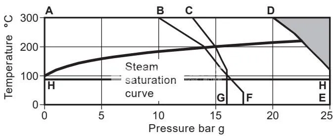
| Maximum Design Pressure (PMA) | 25 bar g @ 100 °C (25 bar g @ 120 °C) |
| Maximum Design Temperature (TMA) - DRV7 | 300 °C @ 17.5 bar g |
| Maximum Design Temperature (TMA) - DRV7G | 90 °C @ 25 bar g |
| Minimum Design Temperature | 0 °C |
| Maximum Operating Temperature (TMO) - DRV7 | 300 °C @ 17.5 bar g |
| Maximum Operating Temperature (TMO) - DRV7G | 90 °C @ 25 bar g |
| Minimum Operating Temperature | 0 °C (consult manufacturer for lower temperatures) |
| Maximum Saturated Steam Operating Pressure | 22 bar g |
| Maximum Differential Pressure (DN15–DN50) | 25 bar |
| Maximum Differential Pressure (DN65–DN100) | 20 bar |
| Cold Hydraulic Test Pressure (Bare Body) | 38 bar g |
| Hydraulic Test Pressure (Internals Fitted) | Maximum 25 bar g |
| Continuous Working Temp - EPDM Diaphragm | 125 °C maximum |
| Continuous Working Temp - Nitrile Diaphragm | 90 °C maximum |
Flow Capacities (Kvs Values)
| Nominal Size | DN15 | DN20 | DN25 | DN32 | DN40 | DN50 | DN65 | DN80 | DN100 |
|---|---|---|---|---|---|---|---|---|---|
| Maximum Kvs | 3.4 | 6.5 | 11.4 | 16.4 | 24 | 40 | 58 | 92 | 145 |
Note: Cv (UK) = Kvs × 0.963; Cv (US) = Kvs × 1.156. Kvs values represent full capacities and should be utilized for sizing downstream safety relief valves.
Applications
- Saturated steam distribution networks and process heating equipment (a WS4 or WS4-3 water seal pot must be installed in the sensing line when handling steam).
- Industrial compressed air distribution lines and dry gas supply systems.
- Non-hazardous and inert industrial gases demanding precise, self-acting pressure regulation.
- Mineral and synthetic oil supply systems (specifying the Nitrile diaphragm suffix N).
- Intermittent liquid supply lines (liquid duties are restricted to intermittent duty; continuous recirculation such as pump bypass is prohibited to avoid cavitation damage).
Materials of Construction
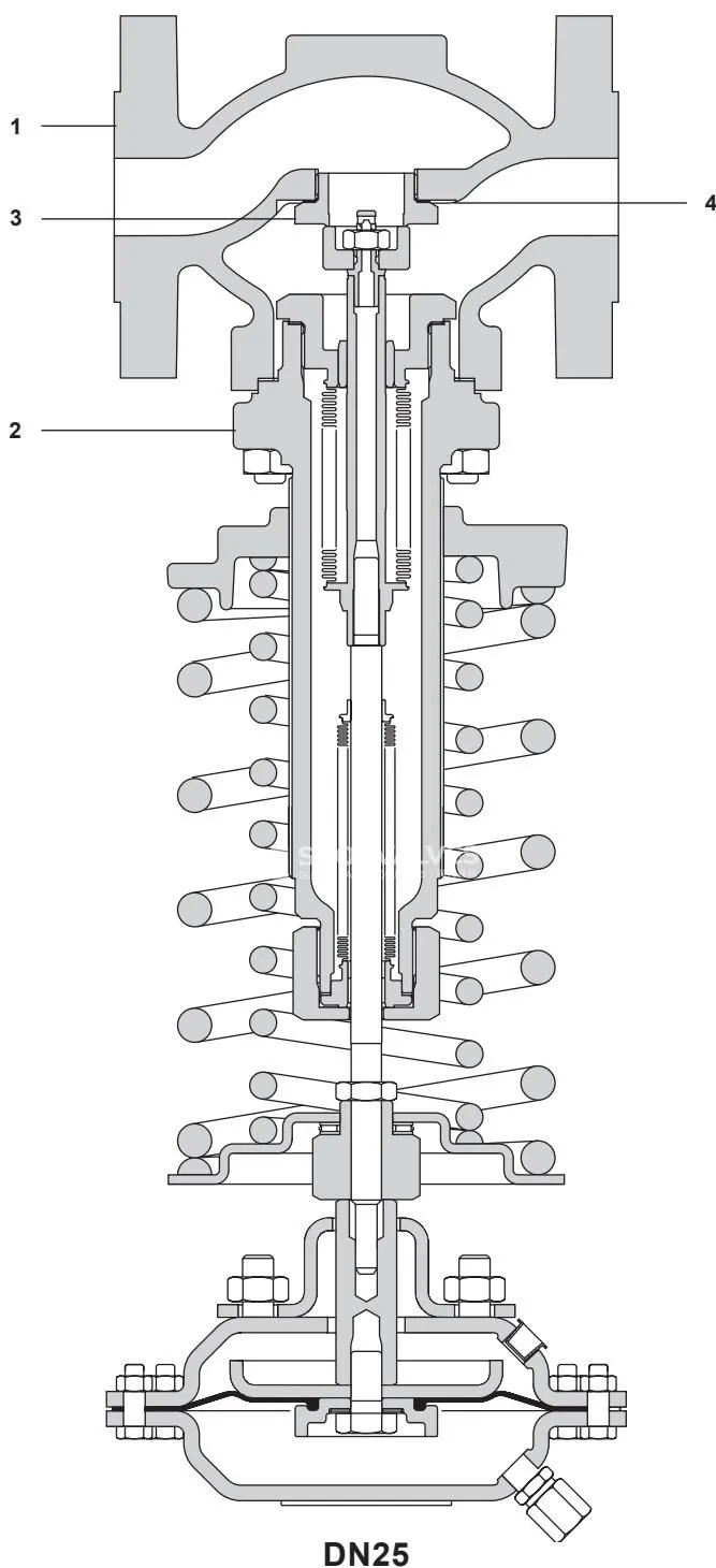
| Item | Part Name | Size Range / Option | Material | Material Standard |
|---|---|---|---|---|
| 1 | Body | DN15 to DN50 | SG iron | DIN 1693 GGG 40.3 |
| 1 | Body | DN65 to DN100 | SG iron | ENG JS 400-18-LT |
| 2 | Bonnet | All sizes | SG iron | DIN 1693 GGG 40.3 |
| 3 | Valve seat | All sizes | Stainless steel | BS 970 431 S29 |
| 4 | Seat gasket | DN15 | Stainless steel | - |
| 4 | Seat gasket | DN20 and DN25 | Mild steel | - |
| 4 | Seat gasket | DN32 to DN50 | Reinforced exfoliated graphite | - |
| 5 | Valve head | DRV7 | Stainless steel | BS 970 431 S29 |
| 5 | Valve head | DRV7G (soft seated) | Stainless steel / Nitrile | BS 970 431 S29 |
| 6 | Valve head screw | DN15 and DN20 | Stainless steel | BS 6105 A2 |
| 7 | Valve head seal | All sizes | Thermoplastic | Arlon 1555 |
| 8 | Bush | DN15 and DN20 | Stainless steel | BS 970 431 S29 |
| 9 | Bush (part of 10) | DN25 to DN100 | Stainless steel | BS 970 431 S29 |
| 10 | Balancing bellows assy | DN25 to DN100 | Stainless steel | AISI 316L |
| 11 | Balancing bellows gasket | DN25 to DN100 | Reinforced exfoliated graphite | - |
| 12 | Bonnet gasket | All sizes | Reinforced exfoliated graphite | - |
| 13 | Bonnet nuts | All sizes | Steel | DIN 267 Pt13 Gr. 8 |
| 14 | Bonnet studs | DN15 to DN40 (M10) | Steel | DIN 267 Pt13 Gr. 8.8 |
| 14 | Bonnet studs | DN50 and DN65 (M12) | Steel | DIN 267 Pt13 Gr. 8.8 |
| 14 | Bonnet studs | DN80 and DN100 (M16) | Steel | DIN 267 Pt13 Gr. 8.8 |
| 15 | Pillars | All sizes | Steel zinc plated | BS 970 230 M07 |
| 16 | Pillar nuts | All sizes | Steel zinc plated | BS 3693 Gr. 8 |
| 17 | Spring adjuster | All sizes | Cast iron zinc plated | DIN 1691 GG25 |
| 18 | Control spring | All sizes | Chrome vanadium | - |
| 19 | Bush (part of 20) | All sizes | PTFE / steel composite | - |
| 20 | Sealing bellows assy | All sizes | Stainless steel | AISI 316L |
| 21 | Sealing bellows gasket | DN15 and DN20 | Stainless steel ‘S’ type | - |
| 21 | Sealing bellows gasket | DN25 to DN100 | Reinforced exfoliated graphite | - |
| 22 | Clamp nut | DN25 to DN100 | Steel zinc plated | BS 970 230 M07 |
| 25 | Lock-nut | DN32 to DN50 | Steel zinc plated | BS 970 230 M07 |
| 25 | Lock-nut | DN15–DN25, DN65–DN100 | Steel zinc plated | BS 3692 Gr. 8 |
| 26 | Spring plate | All sizes | Steel zinc plated | BS 1449 Pt1 HR14 |
| 27 | Needle bearing | All sizes | Steel | - |
| 28 | Setting nut | All sizes | Steel zinc plated | BS 970 230 M07 |
| 29 | Bearing plate | DN32 to DN50 | Steel zinc plated | BS 1449 Pt1 HR14 |
| 30 | Circlip | DN32 to DN50 | Steel zinc plated | - |
| 31 | Mounting plate | DN25 to DN50 | Steel zinc plated | BS 1449 Pt1 HR14 |
| 32 | Actuator housing | Types 1(N) to 4(N) | Steel | DIN 1514 St W24 |
| 32 | Actuator housing | Type 5(N) | Steel | BS EN 10025 S355 J2G3 |
| 33 | Housing screws | Types 1(N) and 2(N) | Steel zinc plated | BS 3692 Gr. 5.6 |
| 33 | Housing screws | Types 3(N), 4(N), 5(N) | Steel zinc plated | BS 3692 Gr. 8.8 |
| 34 | Housing nuts | Types 1(N) and 2(N) | Steel zinc plated | BS 3692 Gr. 5 |
| 34 | Housing nuts | Types 3(N), 4(N), 5(N) | Steel zinc plated | BS 3692 Gr. 8 |
| 35 | Diaphragm | Standard | EPDM fabric reinforced | - |
| 35 | Diaphragm | Suffix ‘N’ | Nitrile fabric reinforced | - |
| 36 | Hex. bolt | All sizes | Stainless steel | BS 6105 A2 |
| 37 | Sealing washer | All sizes | Fibre | - |
| 38 | Diaphragm clamp | All sizes | Stainless steel | ASTM A351 CF8M |
| 39 | Piston | All sizes | Carbon steel zinc plated | BS 1449 Pt1 HR14 |
| 40 | Spindle | All sizes | Carbon steel zinc plated | BS 970 230 M07 |
| 41 | Mounting nuts | All sizes | Steel zinc plated | BS 3692 Gr. 8 |
| 42 | Coupling | All sizes | Steel zinc plated | - |
| 43 | Thread insert | DN15 and DN20 | Stainless steel | DTD 734 |
| 44 | Self-locking nut | DN25 to DN100 | Stainless steel | BS 6105 A2 |
Downstream Pressure Ranges and Actuator Selection
| Range Code | Valve Designation | Actuator Type | Spring Colour | Downstream Pressure Range | Actuator PN Rating |
|---|---|---|---|---|---|
| 1 | DRV7(G)B1(N) | 1 or 1N | Yellow | 0.1 to 0.6 bar (DN32–50: 0.15–0.6 bar; DN65–100: 0.3–0.6 bar) | PN2.5 |
| 2 | DRV7(G)B2(N) | 2 or 2N | Yellow | 0.2 to 1.2 bar (DN65–100: 0.4–1.2 bar) | PN2.5 |
| 3 | DRV7(G)B3(N) | 3 or 3N | Blue | 0.8 to 2.5 bar | PN6.0 |
| 4 | DRV7(G)B4(N) | 4 or 4N | Blue | 2.0 to 5.0 bar | PN16.0 |
| 5 | DRV7(G)B5(N) | 5 or 5N | Blue | 4.5 to 10.0 bar | PN25.0 |
| 6 | DRV7(G)B6(N) | 5 or 5N | Red | 8.0 to 20.0 bar | PN25.0 |
Dimensions and Weights
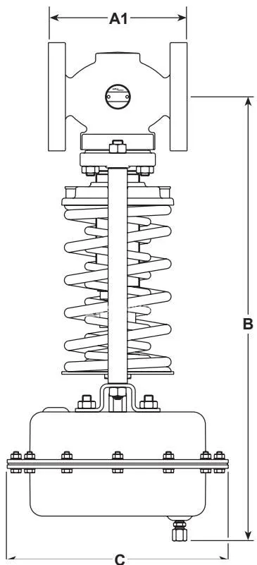
Face-to-Face and Overall Envelope Dimensions (mm)
| Size | Flange PN25 (A1) | Flange ASME 150 (A1) | Screwed (A2) | Screwed Center (E) | Act. 1 (B) | Act. 2 (B) | Act. 3 (B) | Act. 4 (B) | Act. 5/6 (B) |
|---|---|---|---|---|---|---|---|---|---|
| DN15 | 130 | 127 | 88 | 38 | 537 | 511 | 426 | 426 | 411 |
| DN20 | 150 | 143 | 102 | 38 | 537 | 511 | 426 | 426 | 411 |
| DN25 | 160 | 153 | 134 | 51 | 546 | 520 | 435 | 435 | 420 |
| DN32 | 180 | 176 | 144 | 51 | 608 | 582 | 497 | 497 | 482 |
| DN40 | 200 | 198 | 150 | 62 | 608 | 582 | 497 | 497 | 482 |
| DN50 | 230 | 229 | 180 | 71 | 611 | 585 | 500 | 500 | 485 |
| DN65 | 290 | 295 | - | - | 633 | 607 | 522 | 522 | 507 |
| DN80 | 310 | 314 | - | - | 639 | 613 | 528 | 528 | 513 |
| DN100 | 350 | 350 | - | - | 744 | 718 | 633 | 633 | 618 |
Actuator housing diameters (C): Type 1 = 305 mm; Type 2 = 250 mm; Type 3 = 208 mm; Type 4 = 168 mm; Types 5 & 6 = 143 mm.
Component Weights (kg)
| Valve Size | DN15 | DN20 | DN25 | DN32 | DN40 | DN50 | DN65 | DN80 | DN100 |
|---|---|---|---|---|---|---|---|---|---|
| Flanged Body (Yellow Spring) | 10.8 | 11.8 | 14.0 | 18.8 | 20.4 | 23.0 | 31.7 | 38.2 | 53.9 |
| Flanged Body (Blue Spring) | 10.8 | 11.8 | 14.0 | 18.8 | 20.4 | 23.0 | 31.7 | 38.2 | 53.9 |
| Flanged Body (Red Spring) | 11.8 | 12.8 | 15.0 | 20.2 | 21.8 | 24.4 | 33.5 | 40.0 | 56.5 |
| Screwed Body Weight Reduction | -1.7 | -2.2 | -2.2 | -3.6 | -3.9 | -5.5 | - | - | - |
| Actuator Type | 1 or 1N | 2 or 2N | 3 or 3N | 4 or 4N | 5 or 5N |
|---|---|---|---|---|---|
| Actuator Weight (kg) | 12.3 | 6.5 | 3.9 | 2.5 | 2.6 |
Note: Total unit weight equals the valve body assembly weight plus the actuator weight.
Installation Guidelines
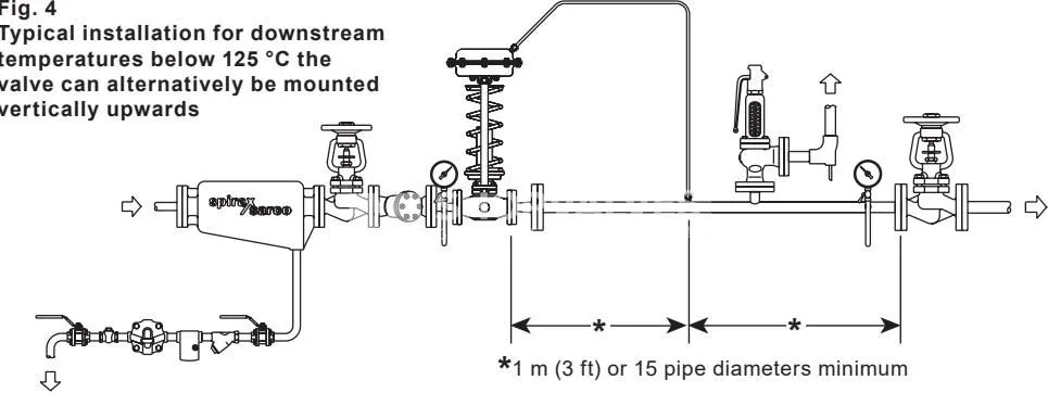
- Position the valve in a horizontal pipe run with the directional arrow on the body pointing in the direction of fluid flow.
- For steam services or media operating above 125 °C, mount the valve vertically downwards with the actuator below the pipework. A WS4 series water seal pot must be installed in the downstream pressure sensing line.
- For operating temperatures below 125 °C, mounting vertically upwards or vertically downwards is permitted.
- Route an 8 mm outer diameter copper or stainless steel sensing line between the actuator coupling and the downstream main. Position the sensing tap at least 1 meter or 15 pipe diameters away from the valve or flow disturbances.
- Protect the valve inlet by flushing system piping prior to commissioning and installing a pipeline strainer. For steam and air lines, mount the strainer on its side to avoid condensate collection.
- In steam lines, fit an upstream separator with a float steam trap, upstream and downstream isolating valves, and pressure gauges on both sides.
- Install an appropriately sized downstream safety valve discharging to a safe location to protect downstream equipment against full DRV capacity in the open position.
- Charge the WS4 / WS4-3 water seal pot with soft water before startup. Open upstream isolation valves gradually to avoid waterhammer.
Commissioning and Maintenance
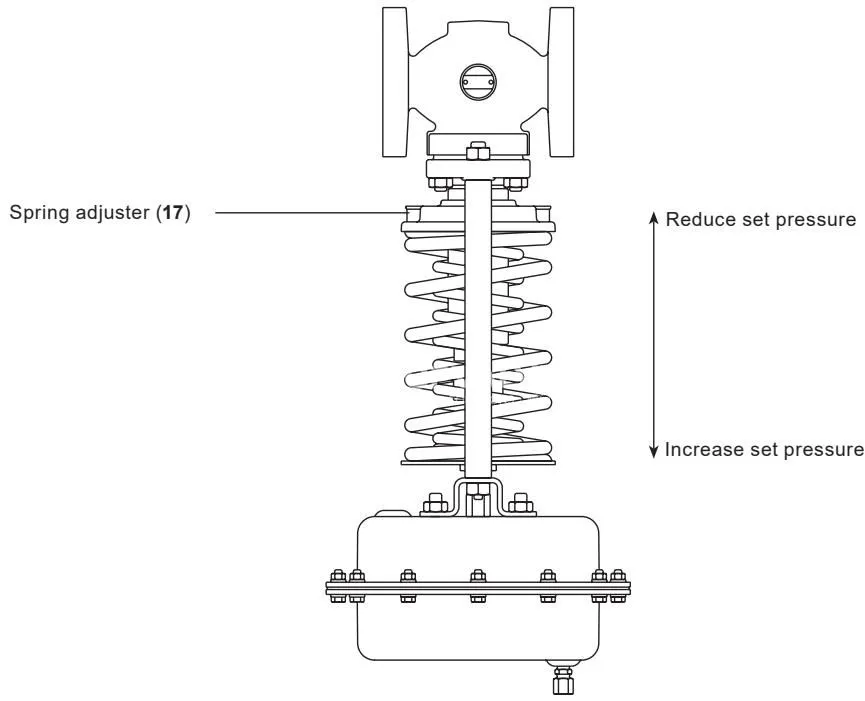
Before servicing, isolate the valve, vent pipeline pressure to zero, and rotate spring adjuster (17) to release spring compression fully. Never rotate setting nut (28) without loosening lock-nut (25), as doing so twists and destroys the stem sealing bellows.
Downstream set point adjustment is achieved using an open-ended spanner (17 mm A/F for sizes up to DN50; 24 mm A/F for DN65 to DN100). Rotating the spring adjuster compresses the control spring to increase downstream pressure, while relaxing tension reduces set pressure.
Maximum Valve Lift Settings
| Valve Size | Maximum Lift (mm) | Setting Nut Adjustment |
|---|---|---|
| DN15 | 4.00 | 2 turns, 4 flats |
| DN20 | 4.75 | 3 turns, 1 flat |
| DN25 | 6.25 | 4 turns, 1 flat |
| DN32 | 7.75 | 5 turns, 1 flat |
| DN40 | 9.00 | 6 turns |
| DN50 | 11.00 | 7 turns, 2 flats |
| DN65 | 12.25 | 8 turns, 1 flat |
| DN80 | 15.75 | 10 turns, 3 flats |
| DN100 | 19.50 | 13 turns |
Recommended Tightening Torques
| Component | Fastener / Item | Valve Size | Recommended Torque |
|---|---|---|---|
| Valve seat (3) | Seat | DN15 | 50 to 55 N·m |
| Valve seat (3) | Seat | DN20 | 105 to 110 N·m |
| Valve seat (3) | Seat | DN25 | 160 to 170 N·m |
| Valve seat (3) | Seat | DN32 | 100 to 110 N·m |
| Valve seat (3) | Seat | DN40 | 175 to 185 N·m |
| Valve seat (3) | Seat | DN50 | 165 to 175 N·m |
| Balancing bellows assy (10) | Threaded body | DN25 | 90 to 100 N·m |
| Balancing bellows assy (10) | Threaded body | DN32 and DN40 | 170 to 180 N·m |
| Balancing bellows assy (10) | Threaded body | DN50 | 220 to 230 N·m |
| Balancing to sealing bellows | Threaded junction | DN25 to DN100 | 2 to 3 N·m |
| Adaptor (23) | Adaptor body | DN25 to DN50 | 55 to 60 N·m |
| Clamp nut (22) | Nut | DN25 to DN50 | 40 to 45 N·m |
| Clamp nut (22) | Nut | DN65 to DN100 | 60 to 65 N·m |
| Bonnet nuts (13) | Stud nuts | DN15 | 15 to 20 N·m |
| Bonnet nuts (13) | Stud nuts | DN20 | 20 to 25 N·m |
| Bonnet nuts (13) | Stud nuts | DN25 to DN50 | 25 to 30 N·m |
| Bonnet nuts (13) | Stud nuts | DN65 | 40 to 45 N·m |
| Bonnet nuts (13) | Stud nuts | DN80 | 60 to 65 N·m |
| Bonnet nuts (13) | Stud nuts | DN100 | 50 to 55 N·m |
| Spindle guide bush (8) | Bush | DN15 and DN20 | 50 to 60 N·m |
| Pillar nuts (16) | Fastener | All sizes | 25 to 35 N·m |
| Sealing bellows assy (20) | Bush | DN15 and DN20 | 175 to 185 N·m |
| Setting nut / lock-nut (28/25) | Nuts | All sizes | 10 to 15 N·m |
| Actuator housing bolts (33/34) | Housing bolts | Types 1, 1N, 2, 2N | 4.5 to 5.5 N·m |
| Actuator housing bolts (33/34) | Housing bolts | Types 3(N), 4(N), 5(N) | 10.5 to 11.5 N·m |
| Diaphragm clamp bolt (36) | Bolt | All actuator types | 23 to 27 N·m |
| Actuator mounting nuts (41) | Nuts | All actuator types | 15 to 18 N·m |
Spare Parts Kits
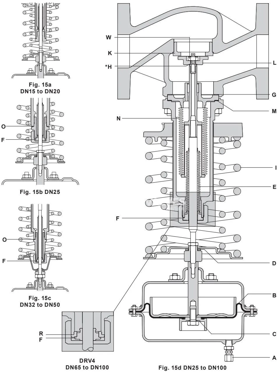
| Kit Description | Sizes Available | Included Items in Kit |
|---|---|---|
| Coupling | All sizes | Coupling (A) |
| Diaphragm kit | All actuator types | Diaphragm (B) and fibre sealing washer (C) |
| Needle bearing | All sizes | Needle bearing assembly (D) |
| Control spring(s) | All sizes | Spring(s) (I) |
| Sealing bellows set | DN15 and DN20 | Sealing bellows assembly (E), sealing bellows gasket (F), bonnet gasket (G) |
| Sealing bellows set | DN25 to DN100 | Sealing bellows assembly (E), sealing bellows gasket (F), adaptor gasket (O on early DN25–50) |
| Seat / head set | DN15 and DN20 | Valve seat (J), seat gasket (K), valve head (L), bonnet gasket (G), head seal (H) |
| Seat / head set | DN25 to DN50 | Valve seat (J), seat gasket (K), head (L), self-locking nut (W), head seal (H), bonnet gasket (G) |
| Valve head set | DN65 to DN100 | Valve head (L), self-locking nut (W), head seal (H), bonnet gasket (G), balancing bellows gasket (M) |
| Balancing bellows set | DN25 to DN50 | Balancing bellows assy (N), balancing bellows gasket (M), bonnet gasket (G), head seal (H), nut (W), sealing bellows gasket (F), adaptor gasket (O) |
| Balancing bellows set | DN65 to DN100 | Balancing bellows assy (N), balancing bellows gasket (M), bonnet gasket (G), self-locking nut (W), head seal (H) |
| Gasket set | DN15 and DN20 | Sealing bellows gasket (F), bonnet gasket (G), seat gasket (K) |
| Gasket set | DN25 to DN50 | Sealing bellows gasket (F), bonnet gasket (G), seat gasket (K), balancing bellows gasket (M), adaptor gasket (O) |
| Gasket set | DN65 to DN100 | Sealing bellows gasket (F), bonnet gasket (G), balancing bellows gasket (M) |