
Description
Product Overview
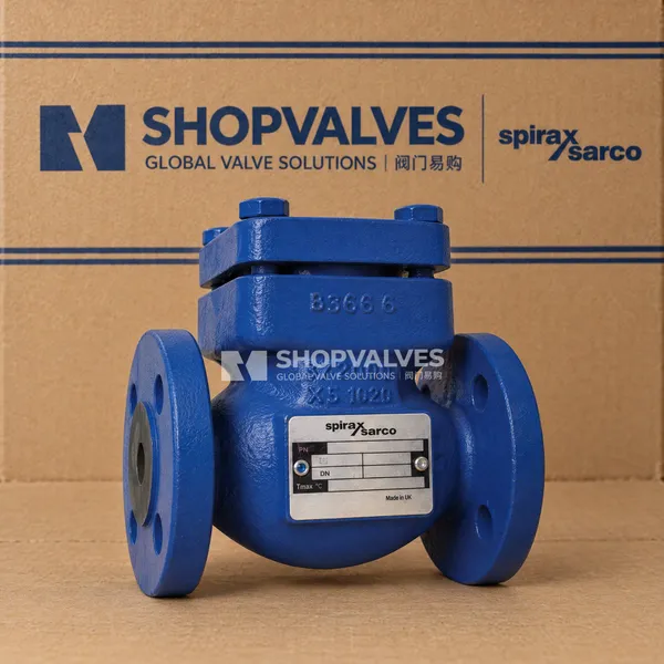
Spirax Sarco LCV3 is a cast iron lift check valve engineered in compliance with EN 12516 and ASME B16.34 to prevent reverse flow in industrial fluid pipelines. Installed in steam distributions and condensate return lines, this valve stops backflow when forward pressure drops, protecting equipment and upstream processes.
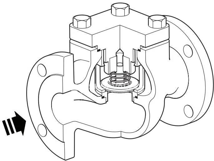
The unit is designed with a top-entry bonnet configuration that enables servicing of all internal components directly in line without unbolting the body from the pipeline. LCV3 features a cast iron body paired with stainless steel trim, while sister models provide alternative metallurgy: LCV4 in cast steel, LCV6 in stainless steel, and LCV7 in SG iron. Shut-off conforms to EN 12266-1: 2003 Rate F, and compliance with the European Pressure Equipment Directive 2014/68/EU covers SEP to Category 1 requirements for Group 2 gases and liquids.
Key Features
- In-line serviceability: top-entry cover access permits inspection and renewal of the disc, spring, seat, and gaskets without removing the valve from the pipework.
- Standard tight shut-off: verified closure performance conforming to EN 12266-1: 2003 Rate F.
- Guided spring closure: positive spring assist shuts the stainless steel disc immediately when flow ceases, eliminating reverse flow before differential pressure can build.
- Design standard compliance: fully calculated and built to EN 12516 and ASME B16.34 specifications.
- Dual mounting flexibility: engineered for operation in horizontal lines as well as vertical pipelines with upward flow.
- Robust graphite sealing: reinforced exfoliated graphite gaskets ensure joint integrity across elevated temperature regimes.
Technical Specifications
| Specification Parameter | Screwed BSP & Flanged PN16 | Screwed NPT & Flanged ASME 125 | Flanged JIS/KS 10 |
|---|---|---|---|
| Body Design Rating | EN 1092 PN16 | ASME 125 | JIS / KS 10 |
| Maximum Allowable Pressure (PMA) | 16 bar g @ 120 °C (232 psi g @ 248 °F) | 13.8 bar g @ 65 °C (200 psi g @ 149 °F) | 13.7 bar g @ 120 °C |
| Maximum Allowable Temperature (TMA) | 300 °C @ 9.6 bar g (572 °F @ 139 psi g) | 232 °C @ 8.6 bar g (450 °F @ 125 psi g) | 220 °C @ 9.8 bar g |
| Minimum Allowable Temperature | -10 °C (14 °F) | -10 °C (14 °F) | 0 °C (32 °F) |
| Maximum Operating Pressure (PMO, Sat. Steam) | 13 bar g (189 psi g) | 10 bar g (145 psi g) | 11.2 bar g |
| Maximum Operating Temperature (TMO) | 300 °C @ 9.6 bar g | 232 °C @ 8.6 bar g | 220 °C @ 9.8 bar g |
| Minimum Operating Temperature | -10 °C (14 °F) | -10 °C (14 °F) | 0 °C (32 °F) |
| Cold Hydraulic Test Pressure | 24 bar g (348 psi g) | 20.5 bar g (297 psi g) | 20 bar g (290 psi g) |
| Available Nominal Sizes | DN15 to DN100 (1/2” to 4”) | DN25 to DN100 (1” to 4”) | DN15 to DN100 (1/2” to 4”) |
| Standard Shut-Off Classification | EN 12266-1: 2003 Rate F | EN 12266-1: 2003 Rate F | EN 12266-1: 2003 Rate F |
Flow Capacities ($K_v$ Values)
| Size | DN15 (1/2”) | DN20 (3/4”) | DN25 (1”) | DN32 (1-1/4”) | DN40 (1-1/2”) | DN50 (2”) | DN65 (2-1/2”) | DN80 (3”) | DN100 (4”) |
|---|---|---|---|---|---|---|---|---|---|
| $K_v$ ($m^3/h$) | 5.0 | 8.3 | 11.0 | 18.0 | 34.0 | 42.0 | 87.0 | 113.0 | 135.0 |
Note: Conversions follow $C_v\text{ (UK)} = K_v \times 0.963$ and $C_v\text{ (US)} = K_v \times 1.156$.
Cracking Opening Pressures (Zero Flow Differential)
| Flow Direction | DN15 to DN25 (1/2” to 1”) | DN32 to DN50 (1-1/4” to 2”) | DN65 to DN100 (2-1/2” to 4”) |
|---|---|---|---|
| Horizontal Installation | 22.5 mbar (0.33 psi) | 24.5 mbar (0.36 psi) | 25.5 mbar (0.37 psi) |
| Vertical Installation (Flow Upwards) | 20.0 mbar (0.29 psi) | 20.0 mbar (0.29 psi) | 20.0 mbar (0.29 psi) |
Applications
- Steam trap discharge lines entering pressurized or elevated condensate return headers, preventing condensate flooding into inactive equipment.
- Pipeline drainage layouts installed after blast-action steam traps (thermodynamic or inverted bucket units), spaced at least 1 m (3 ft) downstream of trap discharge.
- Saturated steam mains drainage legs subjected to backpressure conditions.
- Industrial process pipelines handling Group 2 fluids, including compressed air and process water.
Materials of Construction
| Part Number | Component | Material | Material Standard (PN/BSP) | Material Standard (ASME/NPT) |
|---|---|---|---|---|
| 1 | Cover | Cast iron / SG iron | EN 1561 GJL250 | ASTM A395 |
| 2 | Body | Cast iron / SG iron | EN 1563 GJS400-15 | ASTM A126 Class B |
| 3a, 3b | Gaskets (Cover & Seat) | Reinforced exfoliated graphite | Graphite | Graphite |
| 4, 5 | Seat & Guide | Stainless steel | Grade 431 | Grade 431 |
| 6 | Disc | Stainless steel | BS 316L | AISI 316L |
| 7 | Spring | Stainless steel | BS 316 S 42 | BS 316 S 42 |
| 8 | Cover Bolts | Cast steel | Grade 8.8 | Grade 8.8 |
| 9 | Seat Retainer (Cage) | Stainless steel | BS 316L | AISI 316L |
Dimensions and Weights
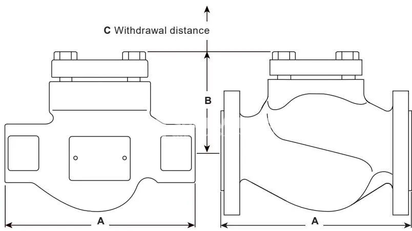
Face-to-Face Dimensions (Dimension A in mm / inches)
| Size | Screwed BSP | Flanged PN16 / JIS 10 | Screwed NPT | Flanged ASME 125 | Withdrawal Clearance C (All Sizes) |
|---|---|---|---|---|---|
| DN15 (1/2”) | 130 mm (5.12”) | 130 mm (5.12”) | 165 mm (6-1/2”) | 184 mm (7-1/4”) | 143 mm |
| DN20 (3/4”) | 155 mm (6.10”) | 150 mm (5.91”) | 165 mm (6-1/2”) | 184 mm (7-1/4”) | 143 mm |
| DN25 (1”) | 160 mm (6.30”) | 160 mm (6.30”) | 197 mm (7-3/4”) | 184 mm (7-1/4”) | 143 mm |
| DN32 (1-1/4”) | 185 mm (7.28”) | 180 mm (7.09”) | 216 mm (8-1/2”) | — | 182 mm |
| DN40 (1-1/2”) | 205 mm (8.07”) | 200 mm (7.87”) | 235 mm (9-1/4”) | 222 mm (8-3/4”) | 182 mm |
| DN50 (2”) | 230 mm (9.06”) | 230 mm (9.06”) | 267 mm (10-1/2”) | 254 mm (10”) | 182 mm |
| DN65 (2-1/2”) | — | 290 mm (11.42”) | — | 267 mm (10-1/2”) | 260 mm |
| DN80 (3”) | — | 310 mm (12.20”) | — | 298 mm (11-3/4”) | 260 mm |
| DN100 (4”) | — | 350 mm (13.78”) | — | 349 mm (13-3/4”) | 300 mm |
Center-to-top dimension (B) is 88 mm (4”) for DN15-DN25, 117 mm (5-3/16”) for DN32-DN50, 166 mm (7-7/8”) for DN65-DN80, and 180 mm (8-1/2”) for DN100.
Product Weights (Approximate in kg / lb)
| Size | LCV3 Flanged (kg / lb) | LCV3 Screwed (kg / lb) |
|---|---|---|
| DN15 (1/2”) | 4.30 kg (9.48 lb) | 3.10 kg (6.83 lb) |
| DN20 (3/4”) | 5.50 kg (12.1 lb) | 4.10 kg (9.04 lb) |
| DN25 (1”) | 5.82 kg (12.8 lb) | 4.10 kg (9.04 lb) |
| DN32 (1-1/4”) | 10.23 kg (22.6 lb) | 7.20 kg (15.9 lb) |
| DN40 (1-1/2”) | 11.43 kg (25.2 lb) | 8.00 kg (17.6 lb) |
| DN50 (2”) | 14.96 kg (33.0 lb) | 10.50 kg (23.1 lb) |
| DN65 (2-1/2”) | 27.04 kg (59.6 lb) | — |
| DN80 (3”) | 29.47 kg (65.0 lb) | — |
| DN100 (4”) | 48.93 kg (108 lb) | — |
Installation Guidelines
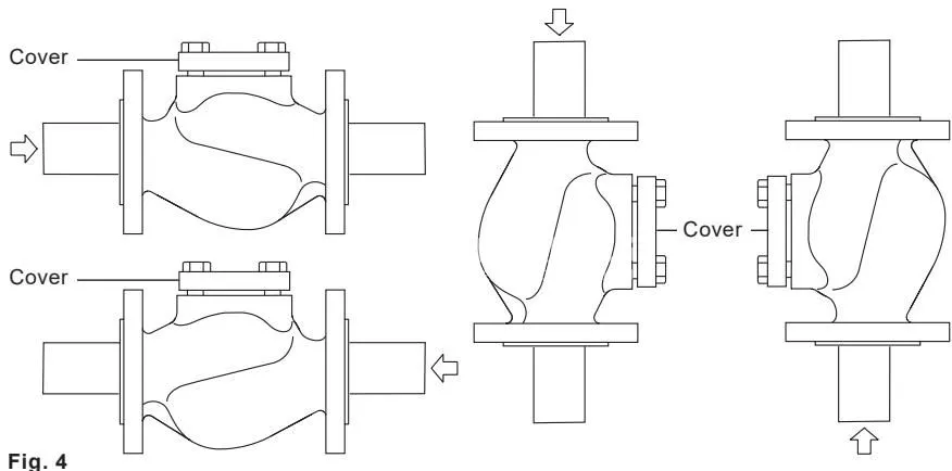
- Ensure fluid direction aligns with the flow arrow cast onto the valve body.
- LCV3 can be installed in horizontal pipelines or in vertical pipework with upward flow.
- Maintain adequate vertical clearance above the top cover (dimension C) to permit cage and internal assembly extraction without strain.
- When installed downstream of cyclic blast-action steam traps (thermodynamic or inverted bucket), install the check valve at a distance of at least 1 m (3 ft) from the trap discharge port.
- Cast iron valve bodies are susceptible to tensile stresses from pipe misalignment; ensure mating flanges are aligned and tighten bolts evenly across opposite diameters.
Maintenance and Spare Parts
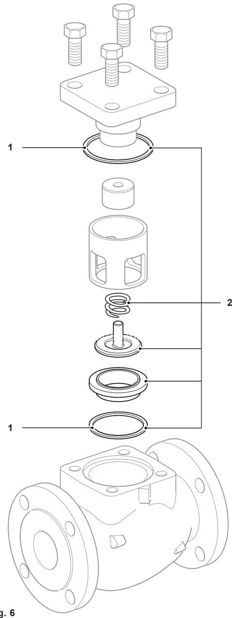
Before undertaking maintenance, isolate the valve and allow pressure and temperature to return to ambient levels. Two spare part kits are available:
- Spare 1 (LCV Gaskets kit): Cover gasket (3a) and seat gasket (3b).
- Spare 2 (LCV Internals kit): Cover gasket (3a), seat gasket (3b), spring (7), disc (6), and seat (4).
Bolting Tightening Torques
| Valve Size | EN Wrench Size (A/F) | ASME Wrench Size (A/F) | EN Thread | ASME Thread | Tightening Torque |
|---|---|---|---|---|---|
| DN15 to DN25 (1/2” to 1”) | 17 A/F | 7/8” A/F | M10 | 1/2” - 13 UNC | 40 - 50 N m (30 - 37 lbf ft) |
| DN32 to DN50 (1-1/4” to 2”) | 19 A/F | 1-1/16” A/F | M12 | 5/8” - 11 UNC | 80 - 90 N m (59 - 66 lbf ft) |
| DN65 to DN80 (2-1/2” to 3”) | 24 A/F | 1-1/4” A/F | M16 | 3/4” - 9 UNC | 90 - 100 N m (66 - 74 lbf ft) |
| DN100 (4”) | 24 A/F | 1-1/16” A/F | M16 | 5/8” - 11 UNC | 70 - 80 N m (52 - 59 lbf ft) |