
Description
Product Overview
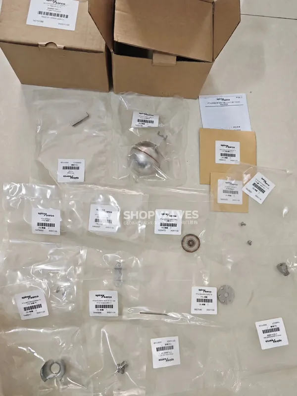
Spirax Sarco FTGS14 Maintenance Kit provides a complete internal rebuild set for Spirax Sarco FTGS14 ball float steam traps sized DN15 (½”), DN20 (¾”), and DN25 (1”). Installing this service kit restores sealing integrity, accurate float lever articulation, and automatic air venting capability on operational steam processes without requiring the removal of the trap body from the piping network.
Each maintenance kit consolidates both the mechanical condensate discharge assembly and the thermal air venting mechanism into a single replacement package. Internal working parts are produced in stainless steel, accompanied by reinforced exfoliated graphite and stainless steel joint gaskets to ensure full factory-standard renewal during scheduled maintenance overhauls.
Key Features
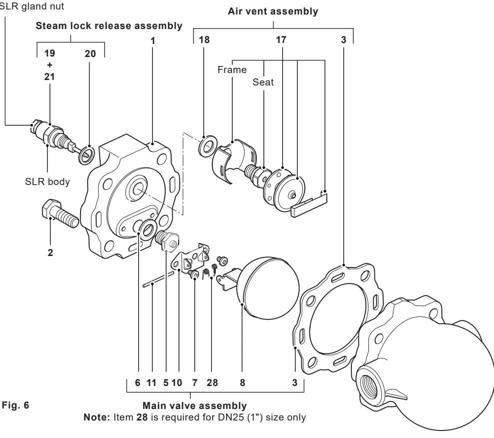
- Factory-matched renewal assembly containing all high-wear internal components: main valve seat, seat gasket, pivot frame screws, complete float and lever assembly, air vent unit, air vent gasket, cover gasket, and valve spring (for DN25 units).
- Stainless steel internal construction offering resistance against condensate erosion and mechanical wear.
- Integrated BP99/32 thermostatic air vent capsule rated for operation with superheated steam up to 150 °C superheat at 0 bar g and 50 °C superheat at 32 bar g.
- In-line service capability permitting complete mechanical refurbishment by unbolting the trap cover without disconnecting piping connections (requiring 105 mm withdrawal clearance for DN15/DN20, or 120 mm for DN25).
- Pressure differential range matching for FTGS14-4.5 (4.5 bar), FTGS14-10 (10 bar), and FTGS14-14 (14 bar) operating conditions.
Technical Specifications
Maintenance Kit Component Breakdown
| Item No. | Component Description | Material | Quantity / Application |
|---|---|---|---|
| 3 | Cover gasket | Reinforced exfoliated graphite | 1 included (contains thin stainless steel support ring) |
| 5 | Main valve seat | Stainless steel | 1 included (matched to 4.5, 10, or 14 bar differential) |
| 6 | Valve seat gasket | Stainless steel | 1 included |
| 7 | Pivot frame assembly screws | Stainless steel | 2 off (M4 x 6 Pozidrive) |
| 8 | Ball float and lever | Stainless steel | 1 assembly |
| 10 | Pivot frame | Stainless steel | 1 included |
| 11 | Pivot pin | Stainless steel | 1 included |
| 17 | Air vent assembly | Stainless steel with BP99/32 capsule | 1 complete unit (includes seat, frame, capsule, spacer, clip) |
| 18 | Air vent seat gasket | Stainless steel | 1 included |
| 28 | Valve spring | Stainless steel | 1 included (fitted to DN25 / 1” size only) |
Host Trap Operating Limits and Ratings
| Parameter | Value |
|---|---|
| Host Body Design Conditions | PN16 |
| Maximum Allowable Pressure (PMA) | 16 bar g @ 120 °C (232 psi g @ 248 °F) |
| Maximum Allowable Temperature (TMA) | 250 °C (482 °F) |
| Minimum Allowable Temperature | -10 °C (14 °F) |
| Maximum Operating Pressure (PMO) for Saturated Steam | 14.6 bar g (211.7 psi g) |
| Maximum Operating Temperature (TMO) | 250 °C @ 13.8 bar g (482 °F @ 200 psi g) |
| Minimum Operating Temperature | 0 °C (32 °F) |
| Maximum Differential Pressure (ΔPMX) | FTGS14-4.5: 4.5 bar; FTGS14-10: 10 bar; FTGS14-14: 14 bar |
| Cold Hydraulic Test Pressure Limit | 24 bar g (348 psi g) |
| Vacuum Service Suitability | Safe for use under full vacuum conditions |
| Fluid Compatibility | Steam, air, or water/condensate (PED 2014/68/EU Group 2 fluids) |
Recommended Tightening Torques
| Item No. | Part | Tool / Thread Size | Tightening Torque (N m) | Tightening Torque (lbf ft) |
|---|---|---|---|---|
| 2 | Cover bolts | 17 mm A/F (M10 x 30) | 47 - 50 | 35 - 37 |
| 5 | Main valve seat | 17 mm A/F | 50 - 55 | 37 - 40 |
| 7 | Main valve assembly screws | Pozidrive (M4 x 6) | 2.5 - 3.0 | 1.8 - 2.2 |
| 17 | Air vent assembly | 17 mm A/F | 50 - 55 | 37 - 40 |
Applications
- Routine preventive overhaul of Spirax Sarco FTGS14 ball float steam traps in industrial steam distribution loops.
- Corrective rebuilding of traps passing live steam due to orifice scoring, seat wear, or float mechanism impingement.
- Elimination of plant air binding or sluggish start-ups caused by degraded thermostatic air vent capsules.
- On-site maintenance servicing across petrochemical, pharmaceutical, food processing, and heating utilities operating Group 2 fluids.
Installation and Maintenance Procedures
Safety Precautions Before Servicing
Before undertaking maintenance, isolate the host trap from both the supply line and return line. Safely vent line pressure to atmospheric level and allow the trap body to cool to ambient temperature to prevent thermal burn hazards. Handle the replacement cover gasket (Item 3) with care: it incorporates a thin stainless steel support ring that can cause laceration if mishandled.
Fitting the Main Valve Assembly
- Undo the four cover bolts (Item 2, 17 mm A/F) and separate the body (Item 1) from the cover.
- Loosen and remove the two Pozidrive assembly screws (Item 7, M4 x 6) to withdraw the complete existing float assembly (Items 7, 8, 10, and 11).
- Unscrew and remove the worn main valve seat (Item 5) using a 17 mm A/F wrench, discarding the used seat gasket (Item 6).
- Position the new seat gasket (Item 6) and thread the new main valve seat (Item 5) into position, tightening to 50 - 55 N m (37 - 40 lbf ft).
- On DN25 (1”) sizes, verify placement of the valve spring (Item 28).
- Position the new float assembly and tighten the two set screws (Item 7) evenly to 2.5 - 3.0 N m (1.8 - 2.2 lbf ft).
Fitting the Air Vent Assembly
- Disassemble the old air vent assembly by removing the spring clip, capsule element, and spacer plate (Item 17).
- Unscrew the old air vent seat using a 17 mm A/F wrench and discard the old gasket (Item 18).
- Clean the joint faces and position the new air vent seat gasket (Item 18), threading the new seat and support frame into place.
- Tighten the air vent assembly seat (Item 17) to 50 - 55 N m (37 - 40 lbf ft).
- Reassemble the spacer plate, fit the new BP99/32 capsule element, and secure with the spring clip.
- Align the air vent unit horizontally so that the frame clears the trap cover profile without physical interference.
Trap Reassembly
- Thoroughly clean all body and cover mating faces.
- Fit the new reinforced graphite cover gasket (Item 3) supplied in the kit.
- Position the trap cover, ensuring the nameplate arrow points downwards and the float arm operates in a horizontal plane for vertical rising and falling motion.
- Reinstall the four cover bolts (Item 2) and tighten progressively in a diagonal sequence to 47 - 50 N m (35 - 37 lbf ft).
- Slowly reopen isolation valves to restore working pressure, checking carefully for joint leakage.
Spares Ordering Reference
When ordering replacement maintenance kits, state the description ‘Maintenance kit’, the connection size of the host trap, the full host trap model designation, and the differential pressure range.
- Example: 1 off Maintenance kit for a Spirax Sarco ½” FTGS14-10 ball float steam trap.