
Description
Product Overview
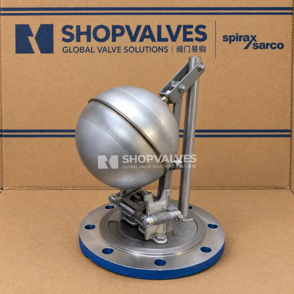
Spirax Sarco MFP14 cover and internal mechanism assembly is a factory-assembled replacement unit designed for Spirax Sarco MFP series automatic condensate pumps. Mounted directly to the top flange of the pump vessel, it converts liquid level displacement into snap-action valve switching to resolve liquid drainage and stall issues across steam-using equipment under vacuum or pressure.
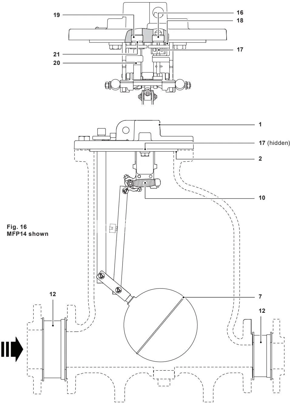
This complete spare assembly comprises the pump cover, synthetic fibre cover gasket, internal snap-action mechanism linkage, springs, valve seats, and float assembly (designated as items 1, 2, and 7 in the factory spare parts schedule). It is supplied ready for drop-in maintenance or whole-unit renewal across SG iron (MFP14), cast steel (MFP14S), and stainless steel (MFP14SS) host pumps.
Key Features
- Factory-calibrated trip points eliminate the need for manual linkage adjustments during field replacement.
- Snap-action over-centre linkage accelerates valve positioning instantly to prevent motive steam blow-through and valve stall.
- High-grade construction pairs an AISI 304 stainless steel float and lever with Inconel 718 or stainless steel actuator springs.
- Integral cover connections include a 1/2” motive supply inlet, a 1” exhaust connection, and a 1/2” BSP plugged port for optional EPM electronic pump monitors.
- Full compatibility covers standard MFP14 models and serves as an upgrade assembly for older pump revisions.
Technical Specifications
| Parameter | Specification |
|---|---|
| Host Pump Compatibility | Spirax Sarco MFP14, MFP14S, MFP14SS |
| Pressure Vessel Design Rating | PN16 |
| Maximum Allowable Pressure (PMA) | 16 bar g @ 120 °C (MFP14, MFP14S); 16 bar g @ 93 °C (MFP14SS) |
| Maximum Allowable Temperature (TMA) | 300 °C @ 12.8 bar g (MFP14); 300 °C @ 10.8 bar g (MFP14S); 300 °C @ 9.3 bar g (MFP14SS) |
| Maximum Motive Inlet Pressure | 13.8 bar g (MFP14, MFP14S); 10.96 bar g (MFP14SS) |
| Maximum Operating Pressure (PMO) | 13.8 bar g @ 198 °C (MFP14, MFP14S); 10.96 bar g @ 188 °C (MFP14SS) |
| Minimum Operating Temperature | 0 °C |
| Ambient Temperature Range (Ex) | -10 °C to 200 °C |
| Motive Fluid Inlet Connection | 1/2” Screwed BSP T Rp (ISO 7-1) or NPT (SW optional for MFP14S/SS) |
| Exhaust Pipe Connection | 1” Screwed BSP T Rp (ISO 7-1) or NPT (SW optional for MFP14S/SS) |
| Electronic Monitor Connection (EPM) | 1/2” BSP T Rp plugged boss on cover |
| Cover Bolt Tightening Torque | 121 to 134 N m (89 to 99 lbf ft) |
| Mechanism Retaining Screw Torque | 38 to 42 N m (28 to 31 lbf ft) |
| Valve Seat Tightening Torque | 129 to 143 N m (95 to 105 lbf ft) |
| Spring Shaft Nut Tightening Torque | 9 to 11 N m (6.6 to 8.1 lbf ft) |
Applications
- Complete replacement of worn, corroded, or scale-fouled internal mechanisms in Spirax Sarco MFP14, MFP14S, and MFP14SS pumps.
- Modernization of older pre-F04 date code mechanisms using the blind-anchor spring retention configuration.
- Scheduled preventative maintenance on condensate recovery units servicing heat exchangers, reboilers, and steam coils.
- Servicing automatic pump installations operating on saturated steam, superheated steam, or compressed air.
Component Materials
| Part Number | Component | Host Model | Material | Material Standard |
|---|---|---|---|---|
| 1 | Cover | MFP14 | SG iron | EN-GJS-400-18-LT (EN JS 1025) |
| 1 | Cover | MFP14S | Cast steel | DIN GSC 25N / ASTM A216 WCB |
| 1 | Cover | MFP14SS | Cast stainless steel | BS EN 10213-4 1.4409 / ASTM A351 CF3M |
| 2 | Cover gasket | All models | Synthetic fibre | Non-asbestos formulation |
| 3 | Cover screws / bolts | All models | Stainless steel | ISO 3506 Gr. A2-70 |
| 5 | Pillar | MFP14, MFP14S | Stainless steel | BS 970, 431 S29 |
| 5 | Pillar | MFP14SS | Stainless steel | BS 970, 303 S31 |
| 6 | Connector rod | All models | Stainless steel | BS 1449, 304 S11 |
| 7 | Float and lever | All models | Stainless steel | AISI 304 |
| 9 | Mechanism lever | All models | Stainless steel | BS 3146 pt. 2 ANC 2 |
| 10 | Actuator springs | DN50, DN80xDN50 | Inconel 718 | ASTM 5962 / ASTM B367 |
| 10 | Actuator springs | DN40 | Stainless steel | BS 2056 302 S26 Grade 2 |
| 14 | Mechanism bracket | All models | Stainless steel | BS 3146 pt. 2 ANC 4B |
| 15 | Bracket retaining screws | All models | Stainless steel | BS 6105 Gr. A2-70 (M10) |
| 16 | Motive inlet valve seat | All models | Stainless steel | BS 970, 431 S29 |
| 17 | Inlet valve stem / plug | All models | Stainless steel | ASTM A276 440B |
| 18 | Inlet valve seat gasket | All models | Stainless steel | BS 1449 409 S19 |
| 19 | Exhaust valve seat | All models | Stainless steel | BS 970 431 S29 |
| 20 | Exhaust valve | All models | Stainless steel | BS 3146 pt. 2 ANC 2 |
| 21 | Exhaust valve seat gasket | All models | Stainless steel | BS 1449 409 S19 |
| 28 | Spring anchor | All models | Stainless steel | BS 970 431 S29 |
Mechanism Replacement and Maintenance Procedures
Removal of Mechanism from Body
- Ensure that all motive supply, condensate inlet, discharge, and exhaust lines are completely isolated and depressurised. Verify that the unit has cooled down to room temperature.
- Disconnect motive inlet and exhaust piping connected to the cover.
- Unscrew the cover retaining bolts. Lift the cover and internal mechanism assembly away from the pump body using the integral eyebolt and note the orientation of the cover relative to the body.
Mechanism Disassembly and Valve Servicing
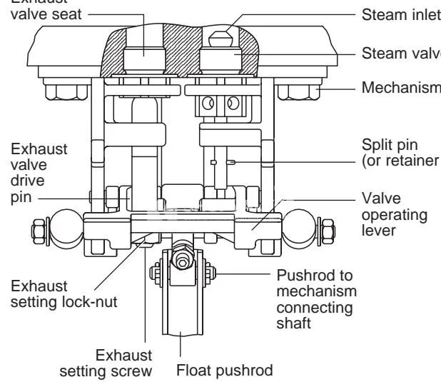
- Remove the retainer nut or split pin from the motive inlet valve stem.
- Disconnect the mechanism from the float connector rod by extracting the split pin and sliding out the pivot shaft.
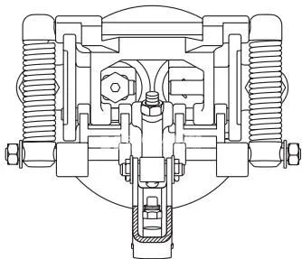
- Loosen and remove the mechanism bracket retaining screws (item 15) to lift the mechanism assembly off the cover.
- Unscrew the inlet and exhaust valve seats along with their washer gaskets. Note that DN25 and DN40 exhaust seats feature a double row of diamond grooves versus a single row on inlet seats; DN50 and DN80 x DN50 inlet seats have radial drillings around each flat.
- Inspect valve and seat contact surfaces for wire drawing, erosion, or solid deposit accumulation. Replace worn seats and always install new stainless steel seat gaskets (items 18 and 21).
Fitting Replacement Mechanism
- Clean gasket seating recesses thoroughly. Thread in new valve seats with new gaskets, tightening both to 129 to 143 N m (95 to 105 lbf ft).
- Position the mechanism bracket over the seats, ensuring the inlet valve stem passes through the guide hole on the bracket. Fasten the two M10 retaining screws to 38 to 42 N m (28 to 31 lbf ft).
- Reconnect the float pushrod with the pin and install a new split pin. If supplied loosely assembled with an elastic band, remove the band immediately after fastening the bracket.
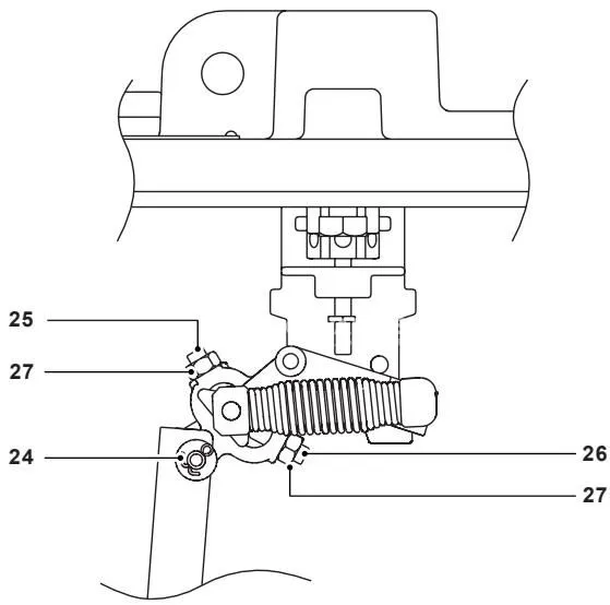
- Reset exhaust valve clearance: hold the operating lever against the stop closest to the cover (exhaust valve closed and seated), turn the set screw until it touches the drive pin, then unscrew it exactly 3-3/4 turns for DN50/DN80xDN50 models (or 2-3/4 turns for DN25/DN40 models) before securing the lock-nut.
Reinstallation on Pump Body
- Thoroughly clean the flange sealing faces of the body and cover.
- Place a brand-new synthetic fibre cover gasket (item 2) into position.
- Lower the cover and mechanism assembly onto the pump body matching the original orientation.
- Tighten the cover bolts evenly in a cross pattern to a final torque of 121 to 134 N m (89 to 99 lbf ft).