
Description
Product Overview
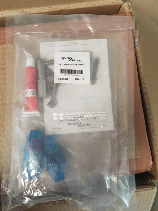
Spirax Sarco MFP14 valve set is an internal replacement component package designed for Spirax Sarco MFP14, MFP14S, and MFP14SS automatic displacement pumps. In condensate recovery and vessel drainage installations, seat wear or particle impingement prevents complete motive fluid shut-off during filling or restricts venting during exhaust, leading to stalled pump cycles. Installing a replacement valve set restores positive motive fluid sealing and unobstructed venting across all pumping strokes.
Key Features
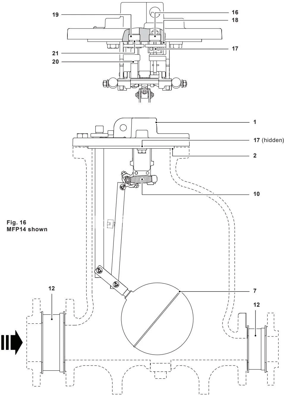
- Comprises all six internal valve elements: inlet valve seat (16), inlet valve stem (17), inlet valve seat gasket (18), exhaust valve seat (19), exhaust valve (20), and exhaust valve seat gasket (21).
- Fabricated from corrosion-resistant stainless steel alloys including BS 970 431 S29 for seats, ASTM A276 440 B for the inlet valve stem, and BS 3146 ANC 2 for the exhaust valve.
- Built with mechanical seat identification features to prevent incorrect assembly during maintenance.
- Compatible with SG iron (MFP14), cast steel (MFP14S), and stainless steel (MFP14SS) pump bodies across DN25, DN40, DN50, and DN80 x DN50 sizes.
Technical Specifications
| Component Item | Part Description | Material Specification | Standard Designation |
|---|---|---|---|
| Item 16 | Inlet valve seat | Stainless steel | BS 970, 431 S29 |
| Item 17 | Inlet valve stem / valve | Stainless steel | ASTM A276 440 B |
| Item 18 | Inlet valve seat gasket | Stainless steel | BS 1449 409 S19 |
| Item 19 | Exhaust valve seat | Stainless steel | BS 970 431 S29 |
| Item 20 | Exhaust valve | Stainless steel | BS 3146 pt. 2 ANC 2 |
| Item 21 | Exhaust valve seat gasket | Stainless steel | BS 1449 409 S19 |
| Seat Tightening Torque | Valve seats into pump cover | 129 to 143 N·m (95 to 105 lbf·ft) | — |
| Bracket Screws Torque | Mechanism retaining screws | 38 to 42 N·m (28 to 31 lbf·ft) | BS 6105 Gr. A2-70 |
| Cover Bolts Torque | Pump cover to body | 121 to 134 N·m (89 to 99 lbf·ft) | ISO 3506 Gr. A2-70 |
| Operating Motive Limits | MFP14 & MFP14S / MFP14SS | 13.8 bar g @ 198 °C / 10.96 bar g @ 188 °C | Saturated/superheated steam or compressed air |
Applications
- Scheduled overhaul and routine maintenance of Spirax Sarco MFP14, MFP14S, and MFP14SS mechanical condensate pumps.
- Resolution of motive supply blow-through into the exhaust line caused by worn or damaged inlet valve seating surfaces (Symptom 3, Cause 3d).
- Rectification of excessive flash steam escaping through the exhaust vent line due to worn or stuck exhaust valves (Symptom 5, Cause 5c).
- Reconditioning internal valving in vented receiver drainage and closed-loop pressure-equalized installations.
Valve Set Inspection and Maintenance Procedures
Disassembly and Inspection Steps
- Disconnect motive steam/gas inlet and exhaust piping from the pump cover.
- Relieve internal pressure, remove cover bolts, and lift the cover and mechanism assembly away from the pump body.
- Remove the shaft (item 24) from the mechanism end of the connector rod and rotate the float and rod assembly to the opposite side of the pillar.
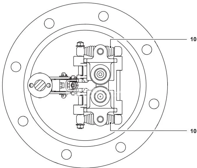
- Remove the spring split pins, washers, and nuts, then slide the spring assemblies off the pivot shafts.
- Remove the locking nut (or split pin) from the inlet valve stem, noting that Loctite 620 adhesive was applied to the threads.
- Remove mechanism bracket retaining screws (38 to 42 N·m) and lift the mechanism bracket away from the cover.
- To remove the exhaust valve from the lever, ease the exhaust-side bracket off the main shaft by lifting the levers away from the bracket feet and tilting the bracket sideways and upward.
- Unscrew both valve seats and remove the inlet valve and washer gaskets from the cover, noting their original positions.
- Visually inspect seating surfaces for scoring, erosion, or foreign debris. Clean or replace the complete valve set if seating wear is detected.
Identification of Valve Seats by Pump Size
- DN25 (1”) and DN40 (1½”): The exhaust valve seat is identified by a double row of diamond grooves; the inlet valve seat features a single row of diamond grooves.
- DN50 (2”) and DN80 x DN50 (3” x 2”): The inlet valve seat contains a series of drilled holes around each flat; the exhaust valve seat is blank.
Reassembly and Setting Procedure
- Ensure seat gasket faces on the cover are clean. Fit new washer gaskets (items 18 and 21) and torque tighten both inlet and exhaust seats to 129–143 N·m (95–105 lbf·ft).
- Place the exhaust valve spring into the exhaust valve body, slide the valve onto the operating lever while holding the spring compressed in the bore, and fit the socket set screw and lock-nut.
- Locate the mechanism over the seats, ensuring the inlet valve stem extends through its guide hole on the bracket. Fasten retaining screws to 38–42 N·m (28–31 lbf·ft).
- Secure the inlet valve stem using a new split pin (bent back around the stem to avoid stroke interference) or a locking nut secured with Loctite 620 adhesive.
- Exhaust Valve Setting: With the operating lever against the stop closest to the cover (exhaust valve held closed against its seat), screw in the set screw until it touches the drive pin. Unscrew the set screw precisely 3¾ turns for DN50 and DN80 x DN50 pumps, or 2¾ turns for DN25 and DN40 pumps. Lock the screw firmly with the lock-nut in this position.
- Fit a new synthetic fibre cover gasket (item 2) and torque tighten the cover bolts in an alternating pattern to 121–134 N·m (89–99 lbf·ft).