
Description
Product Overview
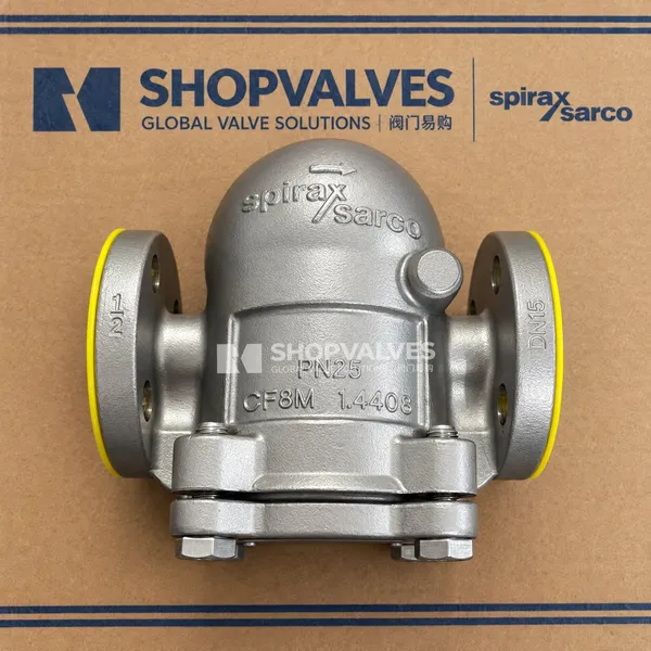
Spirax Sarco FTS14 Flanged is an austenitic stainless steel ball float steam trap engineered with integral flanged connections for industrial steam process pipelines. Installed on process heat exchangers, rotating cylinders, and reboilers, the trap purges air rapidly at startup and drains condensate modulatingly to prevent liquid logging in heat transfer apparatus.
Body and cover casings are cast from 316 austenitic stainless steel (EN 10213-4 1.4408 / ASTM A351 CF8M). Flanged end configurations cover nominal sizes DN15, DN20, and DN25, compliant with ASME B16.5 Class 150, ASME B16.5 Class 300, and EN 1092-1 PN16 / PN25 standards. The cover assembly can be reoriented on site by unfastening four cover bolts, enabling horizontal right-to-left (R-L standard), horizontal left-to-right (L-R), vertical-up, or vertical-down flow configurations.
Key Features
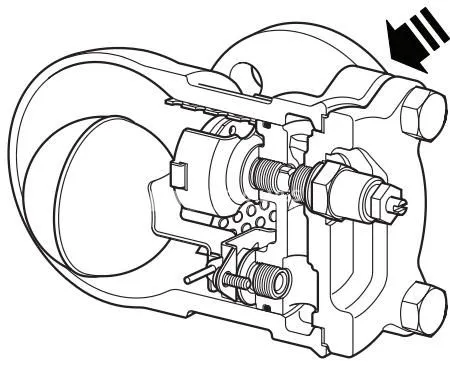
- Continuous condensate discharge via float-lever mechanism modulating in direct response to thermal process load.
- Integral balanced-pressure thermostatic air vent for automatic air discharge at startup.
- Flanged end connections conforming to EN 1092-1 PN16/25 and ASME B16.5 Class 150/300 in sizes DN15, DN20, and DN25.
- Multi-directional body reorientation allowing horizontal and vertical pipe arrangements without replacing the housing.
- Safe operation under full vacuum conditions and cold hydraulic test capability up to 37.5 bar g.
- Optional steam lock release needle valve (FTS14-C) and internal protective strainer screen (FTS14X).
Technical Specifications
| Parameter | Specification Details |
|---|---|
| Body Design Rating | PN25 |
| Maximum Allowable Pressure (PMA) | 25 bar g @ 50 °C (363 psi g @ 122 °F) |
| Maximum Allowable Temperature (TMA) | 300 °C (572 °F) |
| Minimum Allowable Temperature | -20 °C (-4 °F) |
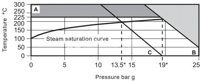
| Maximum Saturated Steam Operating Pressure (PMO) — Flanged PN16, PN25, ASME 300 (Curve A-B) | 19 bar g (276 psi g) |
| Maximum Saturated Steam Operating Pressure (PMO) — Flanged ASME 150 (Curve A-C) | 13.5 bar g (196 psi g) |
| Maximum Operating Temperature (TMO) | 225 °C @ 19 bar g (437 °F @ 276 psi g) |
| Minimum Operating Temperature | 0 °C (32 °F) |
| Cold Hydraulic Test Pressure | 37.5 bar g (544 psi g) |
| Maximum Differential Pressure (ΔPMX) | FTS14-4.5: 4.5 bar (65 psi) FTS14-10: 10 bar (145 psi) FTS14-14: 14 bar (203 psi) |
| Body and Cover Material | Austenitic stainless steel 316: EN 10213-4 (1.4408) / ASTM A351 CF8M |
| Cover Bolts | Stainless steel BS EN 3506 A2-70 |
| Cover Gasket | Reinforced exfoliated graphite with stainless steel support ring |
| Float and Lever Mechanism | Stainless steel BS 1449 304 S16 |
| Valve Seat Material | Stainless steel BS 970 431 S29 |
| ‘O’ Ring | Grey Viton (FDA CFR Title 21, Para 177, Section 2600) |
| Valve Spring (DN25 only) | Stainless steel |
Flange Dimensions and Weights
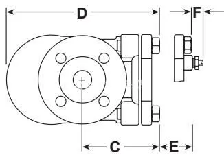
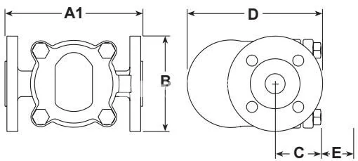
Face-to-face dimensions (A1) and physical weight parameters for flanged variants:
| Size | A1: PN16/25 (mm) | A1: ASME 150 (mm) | A1: ASME 300 (mm) | Height B (mm) | Center-to-Bottom C (mm) | Width D (mm) | Withdrawal E (mm) | SLR Protrusion F (mm) | Flanged Weight (kg) |
|---|---|---|---|---|---|---|---|---|---|
| DN15 (½”) | 150 | 147 | 194 | 97 | 77 | 162 | 135 | 22 | 5.00 |
| DN20 (¾”) | 150 | 147 | 194 | 97 | 77 | 162 | 135 | 22 | 5.00 |
| DN25 (1”) | 160 | 160 | 204 | 113 | 62 | 179 | 145 | 22 | 6.25 |
Applications
- Continuous condensate removal from industrial shell-and-tube or plate heat exchangers connected via flanged piping.
- Drainage of rotating drying cylinders and syphon equipment prone to steam locking (utilizing flanged FTS14-C).
- Condensate line discharge into pressurized return manifolds subject to back pressure or piping elevation.
- Process pipelines in corrosive service environments requiring all-austenitic 316 stainless steel wetted surfaces.
Installation Guidelines
- Install the flanged trap below the equipment condensate outlet, maintaining a drop leg of approximately 150 mm (6”) ahead of the trap inlet.
- Ensure the float arm operates in a horizontal plane so that the float rises and falls vertically; confirm the body marking ‘TOP’ is uppermost.
- Fit a check valve (such as Spirax Sarco DCV41) downstream whenever discharging into return lines with back pressure.
- Maintain minimum clearance for body removal during maintenance: 135 mm for DN15 and DN20; 145 mm for DN25.
Maintenance and Fastener Torques
Prior to servicing, isolate the supply and return lines, vent pressure to atmosphere, and allow the trap to cool. Always replace the Viton O-ring and graphite body gasket upon reassembly.
| Item | Description | Tool / Thread | Tightening Torque (N m) | Tightening Torque (lbf ft) |
|---|---|---|---|---|
| 2 | Cover bolts | M10 x 30 | 20 – 25 | 15 – 18 |
| 5 | Main valve seat | 17 A/F | 50 – 55 | 37 – 40 |
| 7 | Main valve assembly screws | Pozidrive M4 x 6 | 2.5 – 3.0 | 1.8 – 2.2 |
| 9 | Air vent assembly | 17 A/F | 50 – 55 | 37 – 40 |
| 10 | SLR assembly, gasket, and seal | 19 A/F | 35 – 40 | 25 – 30 |
| 17 | Sensor blanking plug | 11 A/F | 15 – 20 | 11 – 15 |