
Description
Product Overview
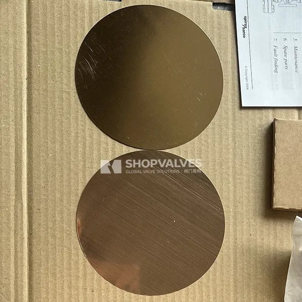
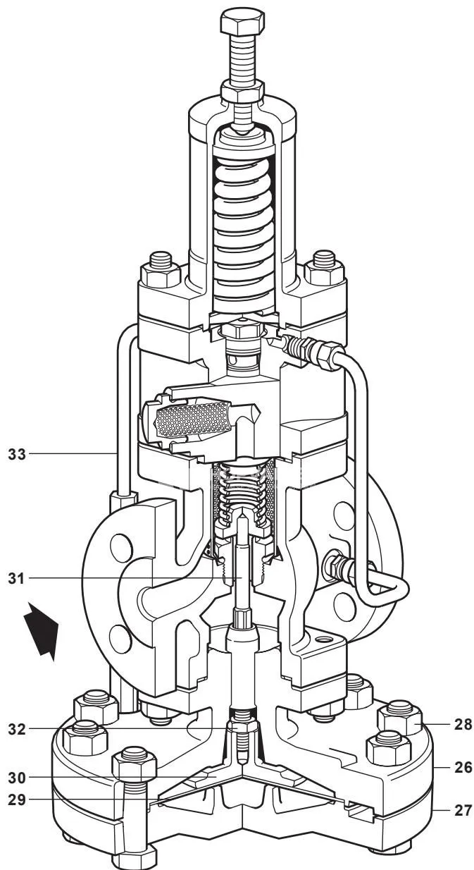
Spirax Sarco DP27 series main diaphragms are phosphor bronze replacement actuating elements engineered for DP27 pilot-operated pressure reducing valves. Clamped between the upper and lower diaphragm chambers below the pipeline axis, these matched dual diaphragms convert pilot loading pressure into linear thrust on the main pushrod. This motion modulates main valve head lift to maintain stable downstream steam, air, or gas pressure.
Over prolonged service or severe operation, diaphragms can suffer from cyclic metal fatigue, rupture, or overstretching. A fractured diaphragm allows actuating media to bleed past the drive chamber, resulting in complete downstream pressure collapse. Overstretched diaphragms cause erratic control hunting under fluctuating loads. Replacing the diaphragm set restores factory responsiveness and shut-off authority without replacing the valve body.
Key Features
- Precision-formed phosphor bronze construction matching BS 2870 PB 102 1980 specifications for elastic compliance and chemical durability in steam systems.
- Factory supplied as a pair (2 off) containing precoated sealant on the outer contact face to establish a leak-tight seal against the chamber flanges.
- Standardized modular sizing structured across three interchangeable dimensional groups covering DN15 through DN50.
- Shared design architecture across DP27, DP27E, DP27G, DP27GY, DP27R, DP27Y, and DP27T models, as well as selected 37D temperature control units.
- Standard component inclusion inside the comprehensive Spirax Sarco DP27 Maintenance Kit (Item A).
Technical Specifications
| Specification Parameter | Technical Data Value |
|---|---|
| Component Designation | Main diaphragm (Item A / Part 29) |
| Standard Quantity Supplied | 2 off (paired set) |
| Material Specification | Phosphor bronze to BS 2870 PB 102 1980 |
| Operating Temperature Limit | Up to 232 °C (saturated steam service) |
| Fastener Torque Requirement | 80 to 100 N m (M12 nuts and bolts) |
| Chamber Fastener Configuration (DN15 to DN32) | Set of 10 off M12 x 50 mm bolts (BS 3692 Gr. 8.8) and nuts (Gr. 8) |
| Chamber Fastener Configuration (DN40 to DN50) | Set of 12 off M12 x 55 mm bolts (BS 3692 Gr. 8.8) and nuts (Gr. 8) |
| Recommended Inspection Interval | 12 to 18 months during routine valve overhaul |
Applications
- Saturated and superheated steam distribution systems utilizing Spirax Sarco DP27, DP27E, and DP27Y pilot-operated pressure reducing stations.
- Compressed air and inert industrial gas pressure control loops equipped with DP27G and DP27GY regulators.
- Remote pneumatically actuated steam pressure control systems using DP27R reducing valves.
- Critical low-pressure steam sterilization and autoclave installations.
Size Grouping and Interchangeability
Spirax Sarco DP27 main diaphragms are grouped into three distinct size bands. Components within the same letter group share full dimensional compatibility:
| Size Group Identifier | Screwed Pipe Connections | Flanged Pipe Connections (EN / ASME / JIS / BS) |
|---|---|---|
| Group a | 1/2” LC, 1/2”, 3/4” | DN15LC, DN15, DN20 |
| Group b | 1” | DN25, DN32 |
| Group c | — | DN40, DN50 |
Installation and Maintenance Procedure
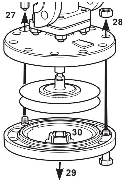
Follow the step-by-step instructions from Section 5.7 of the manufacturer maintenance manual when renewing or cleaning the main diaphragms:
- Isolate the reducing valve upstream and downstream, and ensure internal pressure is zero.
- Loosen the long union nut connecting the control pipework and carefully pull the pipe assembly away from the lower chamber.
- Unscrew the perimeter M12 nuts and bolts (10 off on DN15–DN32; 12 off on DN40–DN50).
- Drop away the lower diaphragm chamber, the two existing diaphragms, the diaphragm plate, and the pushrod assembly.
- Thoroughly clean the lower diaphragm chamber, ensuring all clamping faces and recess grooves are free from scale and debris.
- Replace the diaphragm plate and pushrod assembly. Loosely refit the lower diaphragm chamber on two alignment bolts situated on either side of the union connection to locate the spigot into its recess.
- Place the two new diaphragms together. Ensure the precoated sealant faces outwards toward the chamber clamping faces, then slide the pair into position. If reinstalling cleaned original diaphragms, keep their original orientation and order.
- Push the lower diaphragm chamber home into its locating recess and insert all remaining M12 nuts and bolts. Progressively and evenly tighten across diametrical opposites to a final torque of 80 to 100 N m.
- Reconnect and tighten the long union nut to secure a steam-tight joint.
- Recommission the valve in accordance with commissioning procedures.
Troubleshooting Guide
| Observed Operating Fault | Root Cause Diagnosis | Corrective Action |
|---|---|---|
| Downstream pressure zero or substantially below setpoint | Main diaphragms fractured; pilot pressure escapes without actuating pushrod | Dismantle lower chamber and install a new paired diaphragm set (Steps 27–34). |
| Pressure hunting or wide control oscillation | Main diaphragms overstretched due to hydraulic shocks or overpressure | Inspect diaphragms for permanent deformation; replace with new genuine set. |
| Actuating medium leakage around diaphragm chamber joint | Uneven bolt torque or compromised chamber sealant faces | Clean clamping surfaces, verify spigot alignment, and retorque M12 bolts to 80–100 N m. |